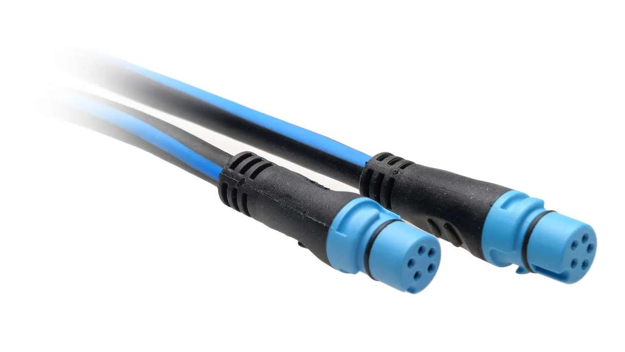
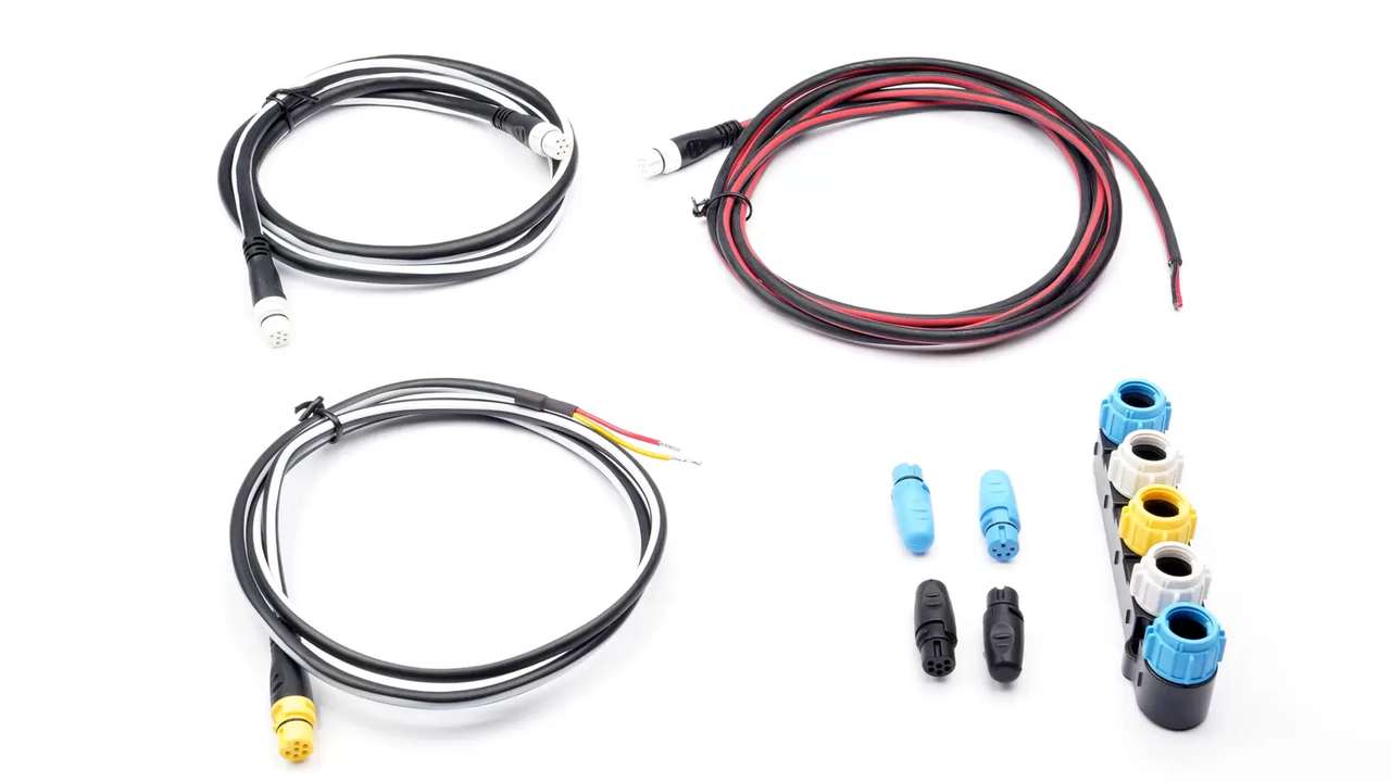
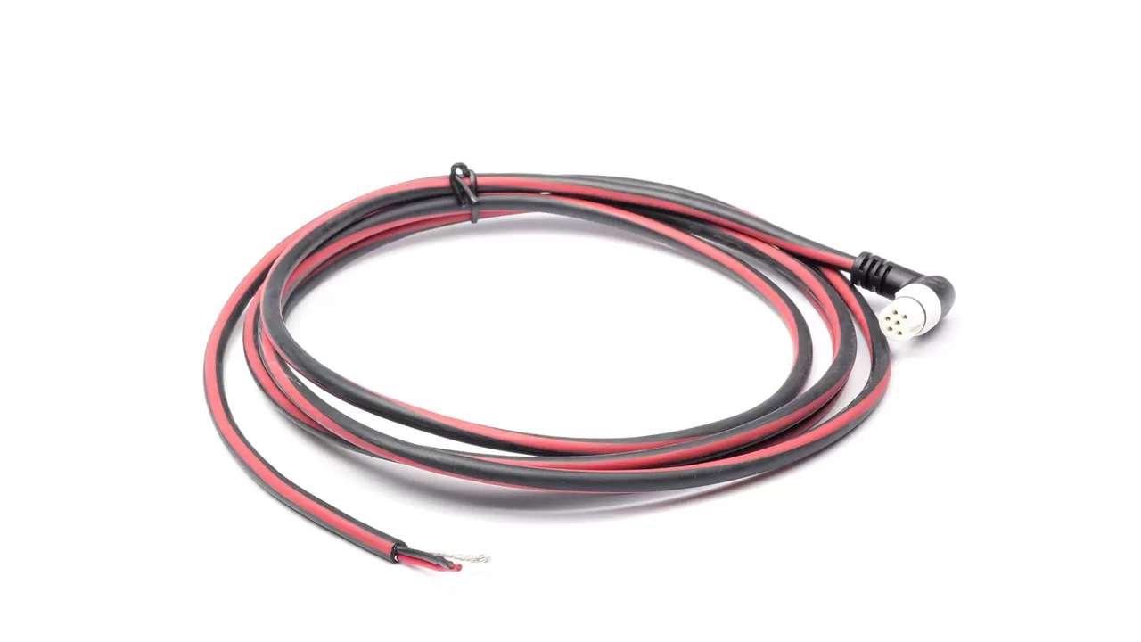
The chartplotter loses the wind sensor, then finds it; the autopilot signals absent and the engine disappears from the data page. Changing all tools can leave the defect identical if the cause is a termination, a voltage drop, a wet connector or a back turned into a star. NMEA 2000 uses a CAN bus to backbone finished; SeaTalk NG Raymarine applies the same architecture with blue cables for the dorsal, white for spurs and dedicated components for power, T, multiple connectors and adapters. Effective diagnosis saves the state first, checks the physical shape of the network and separates power, communication and data selection. Only after you decide if a sensor is really dead.
Do not restart before registering
They are now noted, missing instruments, alarms, motors, active loads, sea status and fault duration. Each display is photographed along with the list of visible devices and selected sources. A reboot can temporarily restore the bus and delete the useful sequence. Software versions and recent changes are saved. If odor, heat, fuse intervened, damaged cable or water in connectors appear, the network is disused and isolated. the procedure does not open sealed products and does not disconnect voltage connectors for random attempts.
Draw what is really installed
The backbone is followed from one end to the other and there are terminators, T, five-way connectors, power supply, adapters and spurs. The original design is verified because refit and additions can have changed the topology. Rolled cables, hidden branches and terminators behind the bridge are identified. The dorsal must remain linear; a star of long branches does not become correct because all knots appear for a few minutes. Each connection is labeled before disconnecting it, avoiding the diagnosis itself to transform an imperfect network into a non-reconstructible network.
Count terminations
With disused network and second procedure, there are two endings at the physical ends of the backbone. A consistent overall resistance helps to confirm the circuit, but does not replace inspection because a short or a device can alter reading. Three terminators attenuate the signal; one leaves the reflective bus. A terminator near the chartplotter is not automatically an end. If a multiple connector closes the back, the final blue port should be correctly identified. After each change, the measure is repeated before refusing.
Separate backbone and spur
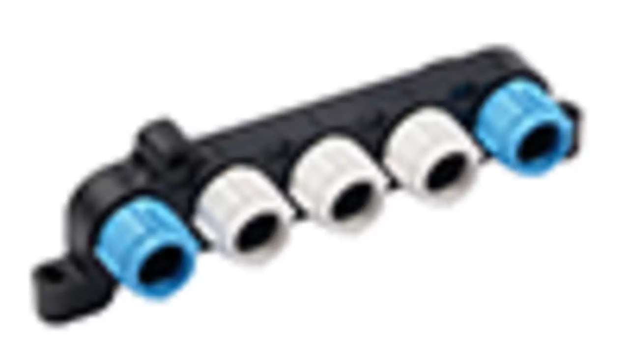
It is checked that the blue and white SeaTalk NG ports are used in the intended role and that the NMEA 2000 DeviceNet cables enter through suitable adapters. A spur is not prolonged until it becomes a second dorsal and the sum of the derivations remains within the applicable limits. A T connected in a creative way can feed a knot while introducing an invalid form. The lengths are measured and the traits are not accessible. Diagnosis first corrects topology, because evaluating software or sensors on a physically incorrect bus produces unstable conclusions.
Network symptoms table
| Symptom | Control | PAYMENT |
|---|---|---|
| All knots disappear | Power and fuse | Fall or short |
| Only aft zone | Backbone and joint | Interrupted treatment |
| Difetto with motor | Voltage and Disorders | Marginal supply |
| Intermittent node | Spur and connector | Humidity or traction |
| Wrong date | Source and instance | Duplication |
| Slow network to boot | Loading and versions | Node or gateway |
Verify single power supply
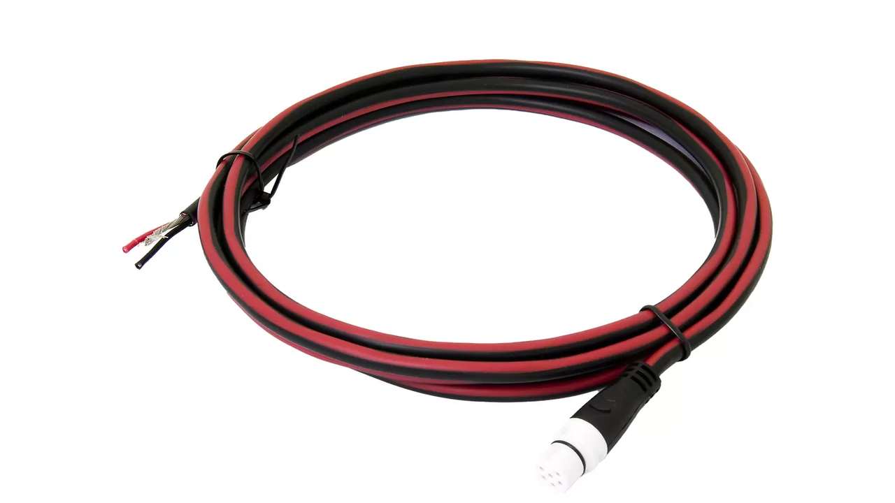
The power cable of the network must come from the expected, protected and switched source. You are looking for added power through a second cable, gateway or device that should not have entered current. Two points can create backfeed and make the drive ineffective. The input voltage is measured and the negative reference is identified. The fuse is controlled by contact and size, without increasing it. If the network turns on itself when its switch is open, the diagnosis stops until the parallel path is detected and correct.
Measure tension at the two extremes
With all the active nodes, the voltage is measured near the power supply and the ends of the backbone, especially where it loses devices. An empty reading does not show the real fall. It is repeated during start-up, radio transmission and insertion of important loads. If the voltage drops only on one side, the power point, the section or a joint may be insufficient. The value is compared with the requirements of the devices, not with an invented threshold. Positive and return are analyzed separately when it serves to locate the loss.
Calculate the load of knots
The declared absorption of instruments, sensors and gateways is added, including additional devices and peak conditions. The T number is not the load. A new display powered separately can still take current from the interface according to its architecture; documentation decides, not the appearance of the cable. The total is compared with cables, power point and protection. If disconnecting some knots the network becomes stable, it does not immediately end that the last one is fault: it could simply have been exceeded the margin or evidenced a pre-existing fall.
Inspect connectors and plugs
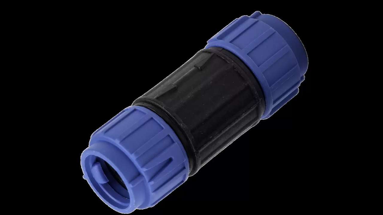
We look for moisture, salt, bent pins, off-site seals, incomplete collars, discoloration and traction cables. Unused doors must be closed as planned. A connector can work dry and break with vibration or condensation. No generic sprays or fats are used that alter materials and contacts. The damaged component is replaced with the compatible component. The groups behind the bridge are fixed, avoiding the weight of the serious beam on the T. After the operation the network is tested only by moving the cables in a controlled way, without forcing the sockets.
Check each spur
The intermittent node is followed by the device at the junction point. Length, continuity, crushing and cable compatibility occurs. For a comparative test a known and authorized spur is used, without changing T and instrument simultaneously. If the fault follows the cable, the cause is located; if it remains on the node, it continues with power and software. A seemingly healthy spur can have a collar not stuck behind a wallpaper. The tests are performed with the dorsal still correctly finished, avoiding confusing a local problem with the effect of an open network.
Split the network without breaking it
To isolate a branch you choose a point that allows you to maintain linear backbone and two terminations, temporarily moving the terminator according to a test scheme. They do not break T randomly leaving an open end. It is observed which knots return stable and narrows the area. Each configuration is disused before editing and documented. If the fault disappears by removing a section, the cause may be knot, cable, connector or load of that branch. The next test separates these elements one at a time, without declaring guilty the first disconnected sensor.
Check adapters and sex DeviceNet
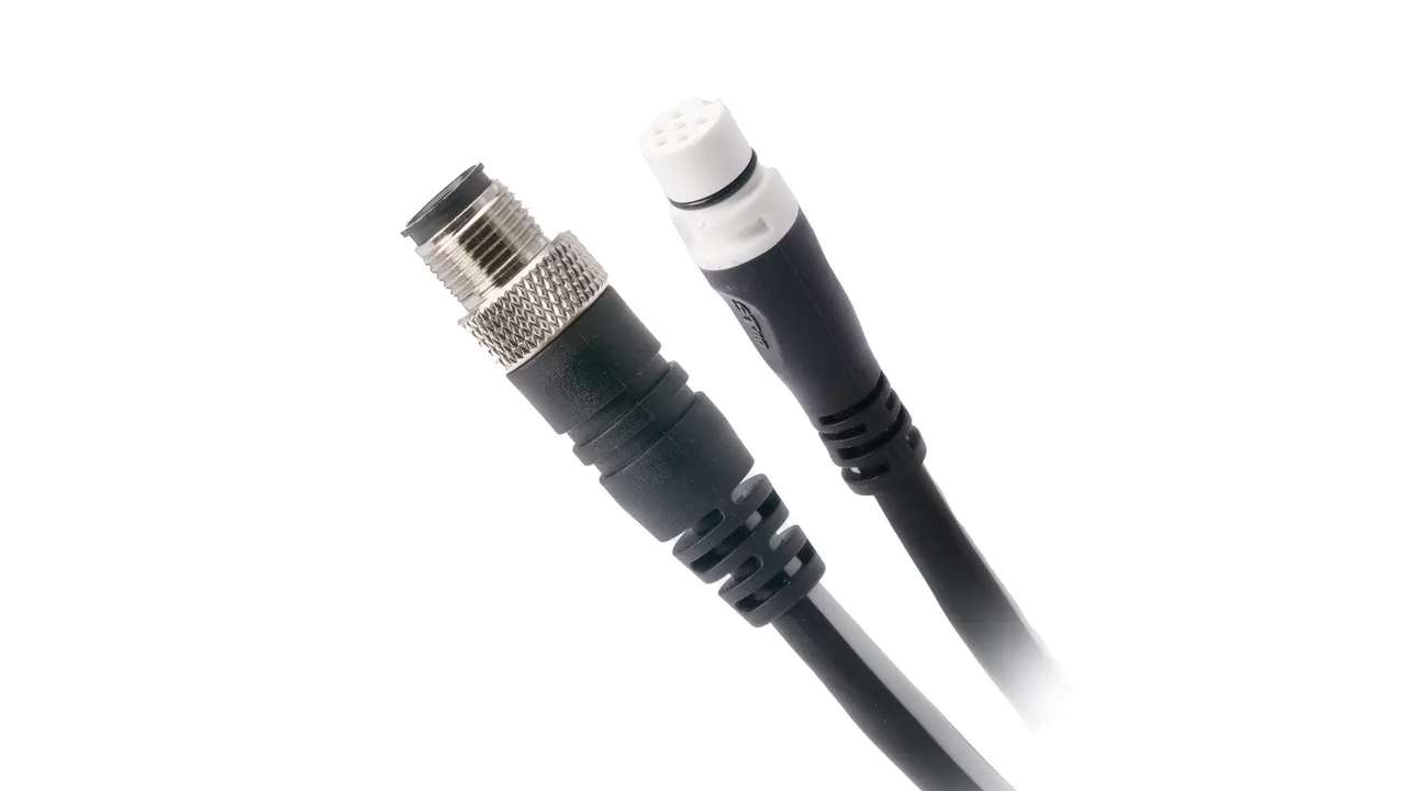
SeaTalk NG–NMEA 2000 adapters exist for different roles and connectors. They control backbone or spur side, male or female DeviceNet and expected physical direction. A chain of adapters can introduce many contacts and hide an invalid branch. The adaptor does not convert data or resolve conflicts of instance. If a third party device disappears, it tries separately cable, adapter and node. The replacement must be of the same functional type, not only mountable. Connections are fixed and protected by water after confirming the electrical result.
Check legacy gateways
SeaTalk 1 or NMEA 0183 converters can depend on the network and feed external devices. It identifies which messages translate, in which direction and with which speed. A DSC VHF that loses location can depend on the gateway while not appearing as the NMEA 2000 node. LED and official diagnostics are observed, then you measure power. Duplicate data cycles are deleted by disabling one source at a time. The gateway is only updated after stabilizing the physical bus. A passive cable does not replace a converter when protocols are different.
Read list nodes and meters
The available diagnostic displays and tools show devices, versions, instances and sometimes network errors. You save a complete list when the system works and compares it during the defect. A node that changes identity or appears several times suggests configuration or gateway; many nodes that disappear together suggest power or backbone. The absence of errors displayed does not exclude a short fall. Logs are related to electrical measurements and onboard loads. Diagnosis does not stop at the green screen if the operating problem remains reproducible.
Separate network from data selection
If the sensor is visible but the chartplotter shows a different value, source, priority and instance are checked. Twin motors, tanks, GPS and prora sensors can transmit similar parameters. The display may have kept a previous selection after an update. It occurs that autopilot, tools and chartplotter use the same source when necessary. You do not delete a healthy sensor to solve a poorly configured menu. Before changing instances you save the configuration and document the effect on other devices, avoiding that the correct data on a page becomes wrong elsewhere.
Try startup and real loads
The network is started cold with all knots, then with controlled sequences. Engines, radars, VHFs, pumps and utilities that coincided with the defect. Tension is observed to the leaders, nodes list and data stability. Vibrations and temperature can make intermittent a joint that in port remains perfect. The test lasts long enough to cross the typical period of failure. You do not consider solved a problem because the sensor appeared once. The outcome must remain stable during a representative operational condition and after more complete reboots.
Check software after the electric
When topology, terminations and power are compliant, official versions and compatibility are compared. Updates are performed with stable voltage, one component at a time and with configuration backup. It does not update in the middle of an electrical diagnosis to hope that the problem disappears. After the update you will review instances, sources, alarms and functions of the autopilot. A legacy node may require a gateway or a specific version; the decision comes from the compatibility matrix, not from age. The rollback, if supported, remains a documented procedure and not improvised in navigation.
Testing Degraded Mode
It simulates loss of non-essential sensors without opening the backbone. The crew verifies that position, depth, and government have known alternatives or a safe procedure. Alarms must be recognizable and not simply silenced. You try rebooting from the network switch and recovery of nodes. If the engine gateway is isolated, navigation functions should not depend on a hidden power supply through it. The degraded mode is updated after each refit and is part of the delivery, there is no supposition of the technician.
Document repair
The final scheme shows backbone, two ends, terminators, power supply, protection, T, doors, adapters and spurs. There are tensions to the garments, resistance to network off, absorption, nodes list, versions and sources. The replaced component and the proven cause are dated. The photographs behind the bridge help to reconstruct the path without pulling cables. If the topology was correct, the old pattern is marked as outdated. This documentation allows to verify that a future addition would not recreate the same star or reactive a second power.
Preventive maintenance
Periodically, fixtures, humidity, plugs, collars, rubbings and tension are checked at distant points. The nodes list is compared with the reference and each occasional disappearance is recorded. After work on engine, dashboard or tree, no one has moved a shutter or used a door as an accessory feed. Software updates follow a controlled window. A connector is not tightened by pulling the cable. Prevention transforms an intermittent defect into a measurable variation before prora, wind or position disappear during a manoeuvre.
Procedure verdict
When the chartplotter loses sensors, changing tools is the last decision, not the first. It starts from real scheme, two terminations, distinction between backbone and spur, one single power and voltage measured to the garments. Then isolate connectors, cables, adaptors, gateways and load without breaking topology. Only on an electrically stable network are evaluated versions, instances and data sources. SeaTalk NG and NMEA 2000 are reliable if treated as a full bus. A documented diagnosis returns visible knots over time and prevents a healthy sensor to be replaced to hide a defective dorsal.