
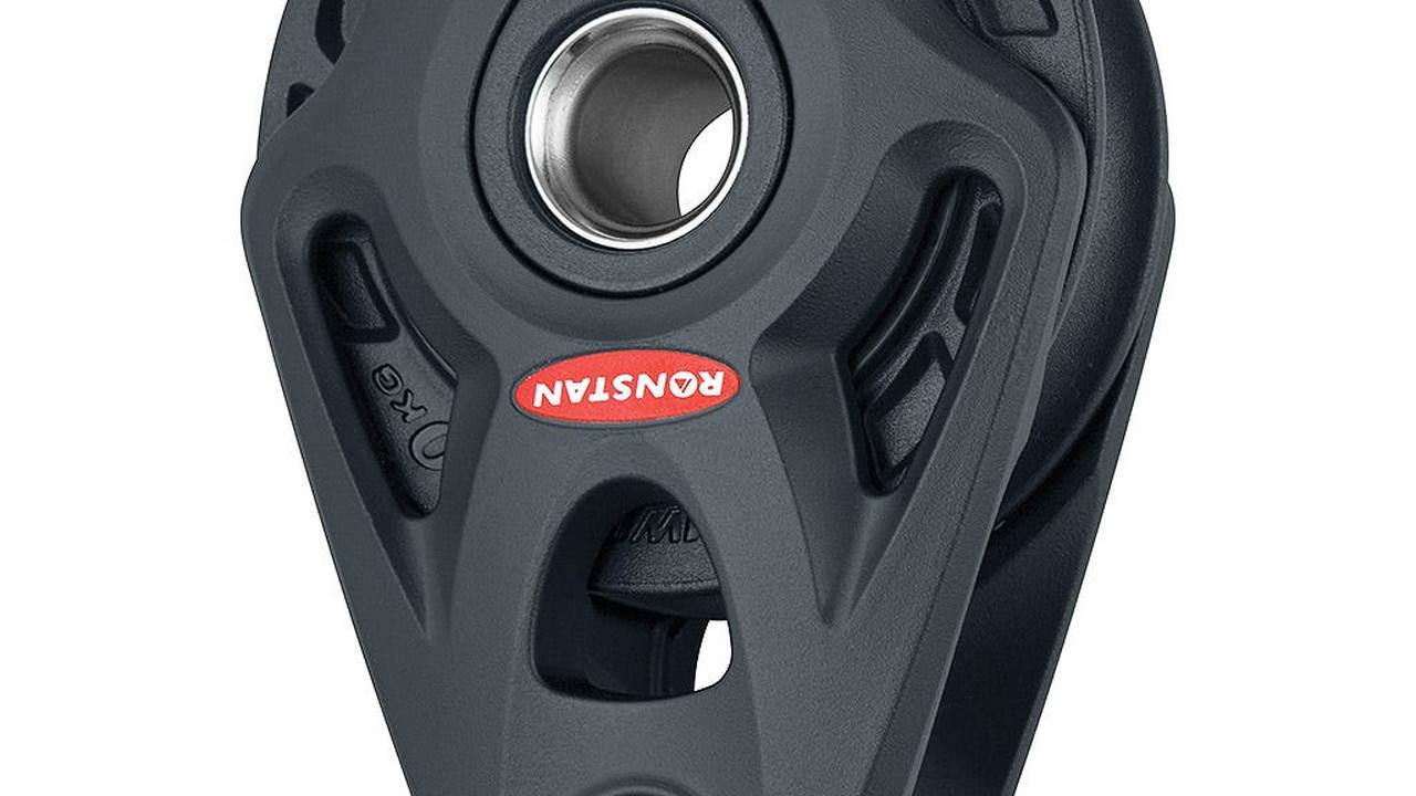
If a top stays tough, mount a larger draft can hide the defect without correcting it. The Ronstan Core series 75 and 100 cover challenging enclosures with pulleys of 75 and 100 mm, but each code has load, attack and fixtures. this analysis separates identification, assembly and test: first you control maneuver and result, then you choose the model, finally the system under fire. The goal is not to turn a vacuum pulley, but to achieve a smooth, structurally correct and inspectable line.
Identify engraved or reported code
It is not enough to recognize a Core cheek. Note the full code and compare it with type of head, pulley and base. The RF74100 is the single series 75; the RF104100 is the single series 100. Versions from drizza, tree base, stand-up and foot can look affine but different limits. If the code is not readable, it measures pulleys, pin and fixation without loading the piece. A spare is chosen only when the configuration is identified without ambiguity.
Measure top and throat before arming
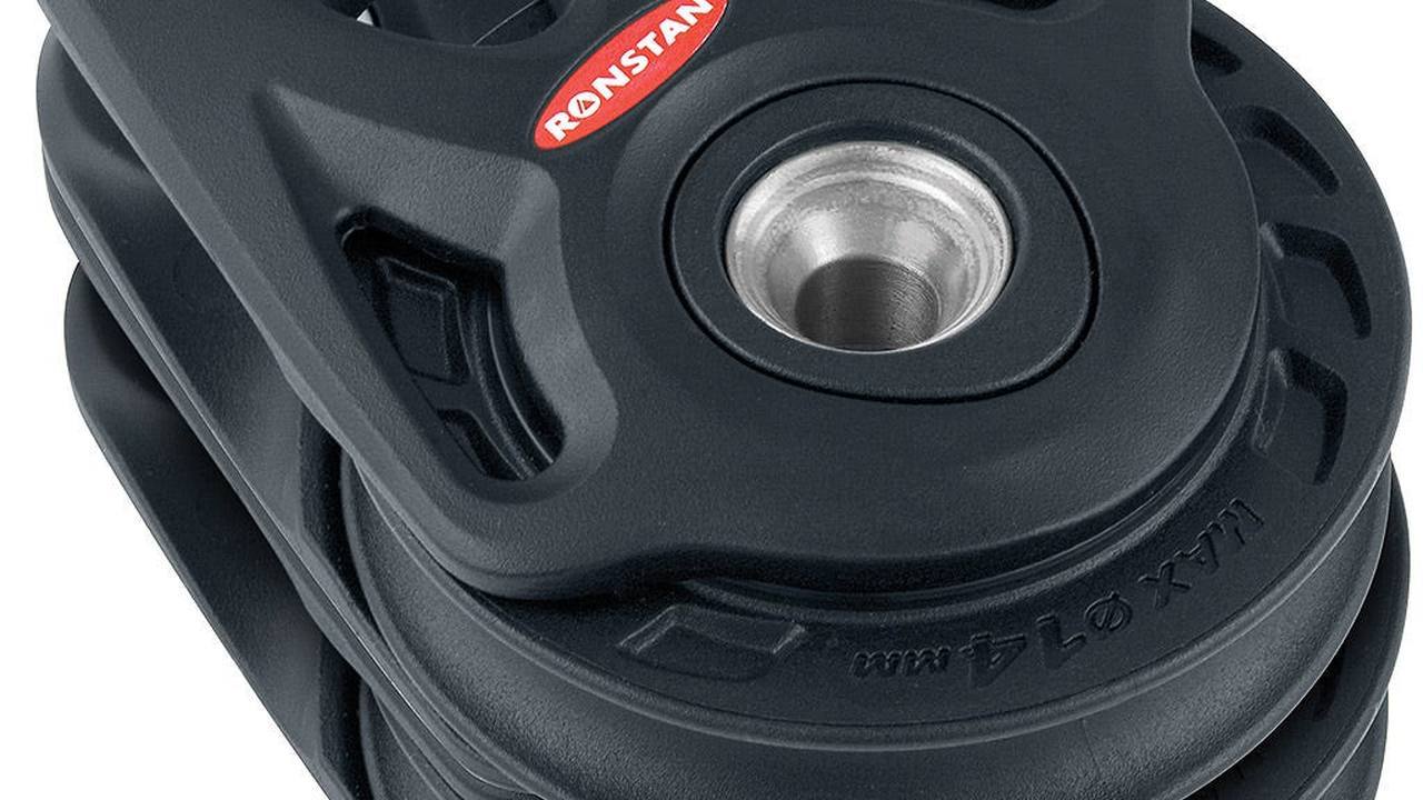
The 75 series accepts top up to 14 mm; the 100 series arrives at 18. The maximum value does not guarantee that each construction works the same way. Controls real diameter in multiple points, stiffness, impiombatura and shoe status. The top must sit in the throat without touching the cheeks stably and must cross the reference also wet. For wire rope or specific combinations, the alloy pulley is required: do not use the single standard only because the diameter seems compatible.
| Control | Series 75 | Series 100 | Required statement |
|---|---|---|---|
| pulley | 75 mm | 100 mm | throat consistent with the top |
| top top | 14 mm | 18 mm | free passage under fire |
| single | MWL 1.500 kg | MWL 3.250 kg | documented margin |
| stand-up | 4 × 6 mm | 4 × 8 mm | correct plate and screws |
| foot | 2 × 10 mm, 62.5 mm | 2 × 12 mm, 81 mm | unmodified holes |
Rebuild the deviation angle
Mark the incoming and outgoing branch in extreme positions. The base receives the result of the two tensions, not the only shot on one end. If the top changes angle during the manoeuvre, observe the most heavy condition. A rock also produces dynamic peaks; a straightness can maintain a prolonged static load. The series is chosen on the calculation of the circuit and on the expected margin, never on the length of the boat or on the visual impression that a larger body is automatically safe.
Compare precise code load
The single series 75 declares 1,500 kilograms of workload and 3,000 breakage. The single series 100 declares 3.250 and 7.500 kilograms. These values do not automatically switch to stand-up, foot or system with other accessories. For example, the 100 series stand-up declares 3,000 kilograms of work and 6,000 breaks. It records the lowest limit of the entire chain, including grill, pin, plate, vice, terminal and structure.
Check the discharge universal head
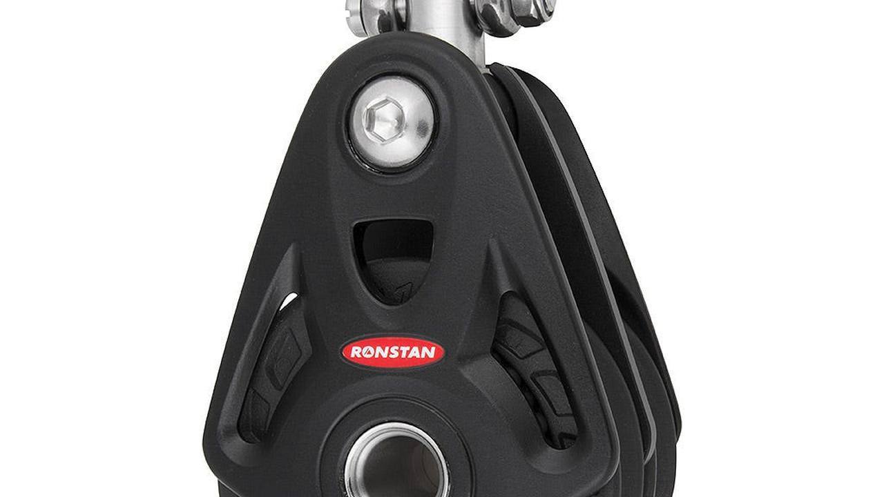
On the single series 75 the head offers three-axis joint and 360-degree rotation, favored by a brass washer. It can be left free or blocked at zero or 90 degrees with a 2.5 mm hexagonal key. The single 100 series also allows the two positions. Move the completely unloaded circuit head, check the stop and simulate the direction under fire. No position should bring cricket, pin or cheek against the top or a blanket element.
Check the hub and eventual arricavo
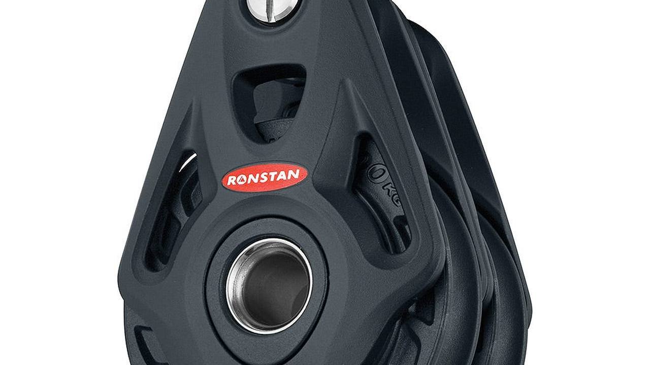
The central hole can serve as a recess or binding point in the planned configuration. On series 75 the line used in this function should not exceed 13.5 mm. Check that the branch does not vent the pulley and that knot or wrapping stay out of the passage. An arricavo increases the branches that charge the body and modifies the ratio of the hoist. Do not insert improvised hardware into the hub: the rigid contact can concentrate the load in a zone designed for a line.
Examine cheeks, pulley and bearing
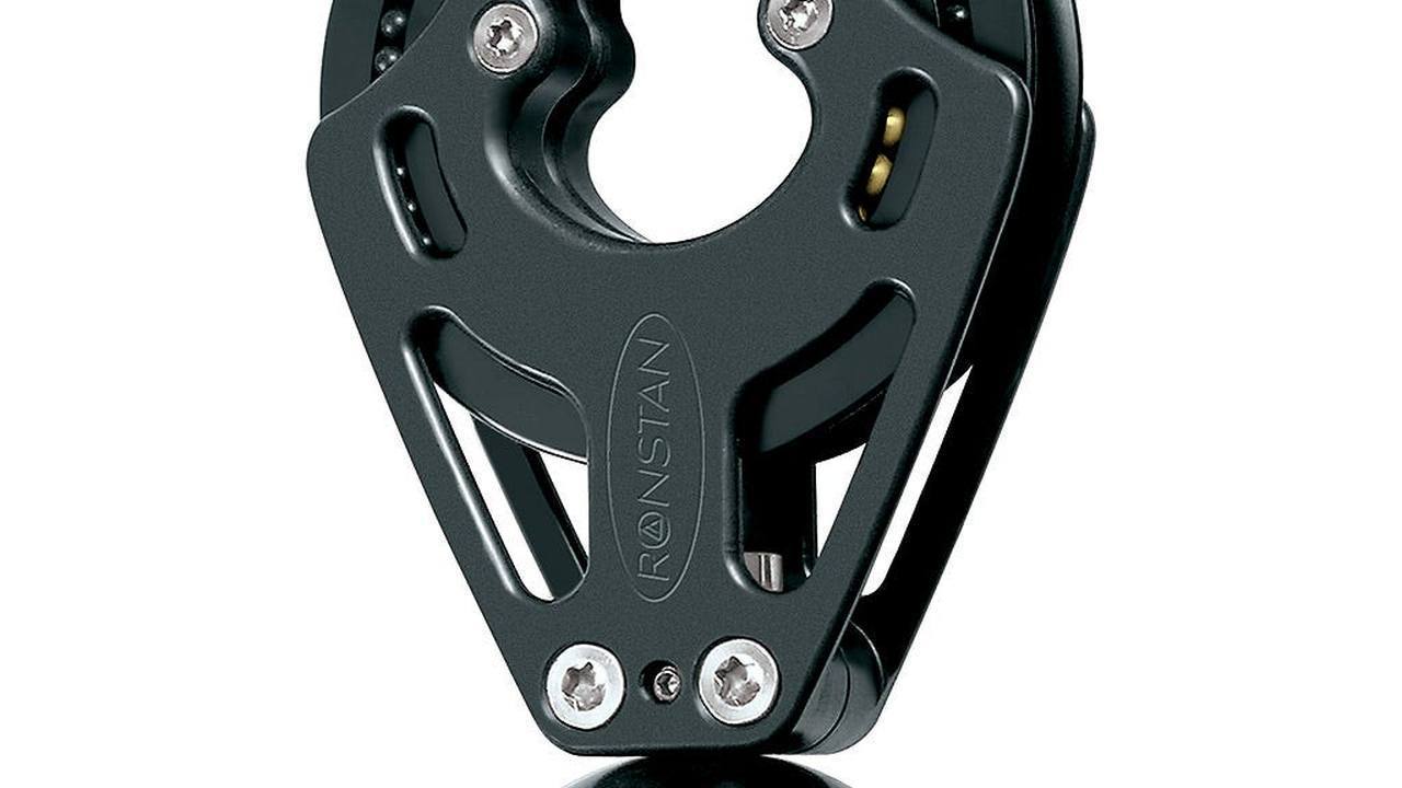
Alloy cheeks must be devoid of cracks, folds and deep engravings. Rotate the pulley by looking for hard points, then push it sideways to locate abnormal play without forcing it. The Core system is designed for high dynamic and static capacity; in the 100 series the spheres also contrast side thrusts. This does not make a top off axis acceptable. Polished signs on one cheek or asymmetrical wear of the throat indicate a path to be corrected before the reassembly.
Check the pin of the straight version
The RF74108 series 75 has 8mm removable pin and acetalic roller for line impiombata; it can connect directly to the frog tablet in a straight 2:1. Check thread, hold, roller and width of the support. The load should not focus on a board. Download the pin without hits and check that the terminal cannot slide on the thread. After the first load, download again and look for unwanted prints or rotations.
Measure the base of the tree
The RF104108A 100 series uses 12mm pin and leaves 22mm between the head cheeks. To reach the 3.250 kilograms of work and 7.500 of declared breakage, the load must be distributed evenly along the pin. A 22 mm cylindrical collar or a 22 mm wide plate or tangon is indicated. If the attack is tighter, do not compensate with random washers: stop mounting and check the expected geometry.
Inspect the stand-up base 75
The RF74140 uses four 6mm fixtures. The pulley is 75 millimeters, the maximum top from 14 and the declared workload is 1,500 kilograms. Check that the base padeye does not move and that the elastic bellows is intact. The bellow keeps the body lifted and limits the noise when the top is discharged, but does not transfer the load. Under deck there must be support, washers or counterplate and laminated consistent with the resulting.
Class check and lock on stand-up 100 series
The RF104140 requires four 8mm fixtures. It declares 3,000 kilograms of work and 6,000 breakage; to reach the break value Ronstan recommends A4-80 DIN 7991 screws. Identify the marking of the defect, check that the heads sit properly and that the dice are accessible. Do not replace the class with a generic stainless steel screw. Locking and sealing follow the mounting specifications, avoiding crushing sandwiches or deforming the base.
Control interasses and foot support series 75
The RF74151 uses two 10mm fixings, spaced 62.5mm. It declares 1,500 kilograms of work, 3,000 breakage and weighs 259 grams. Measure the existing holes and refuses sunshades or ovalizations. The shaped cheeks allow limited variations in the line, not a continuous lateral input. Place the foot temporarily, arm the top and observe the alignment to the entire race before sealing. Under load the base should not turn on the two only points.
Check the two 100 series foot fixtures
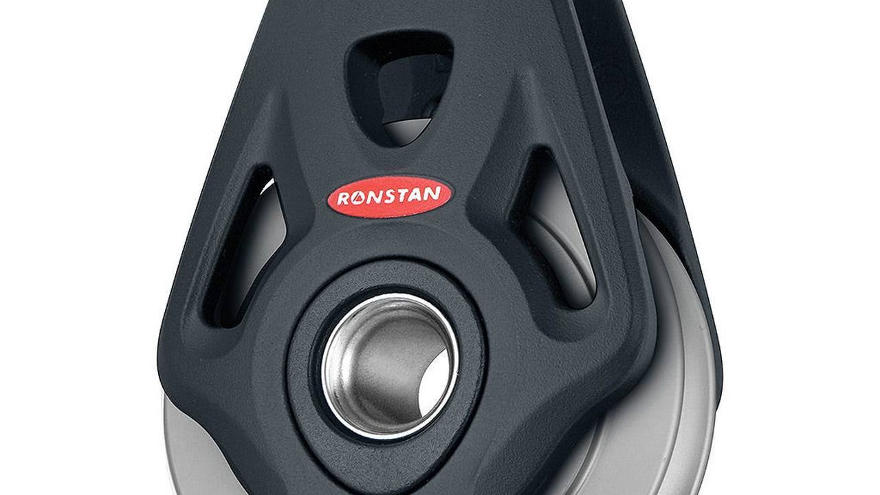
The RF104151 requires two 12mm fixeds with an inter axis of 81mm. It weighs 700 grams and declares 3.250 kilograms of work and 7.500 breakage. Check edge distance, support surface and counterplate capacity to distribute the resulting. Two larger bolts don't make a thin blanket fit. If the support is sandwiches, the area must be prepared to avoid crushing and water input according to the structural project of the boat.
Leave drainage and access for washing
Salt and sand increase friction and hide the first signs of wear. The body must be rinsed with fresh and dried water. Do not close the base in a compartment without drainage and do not cover pins or dice with permanent finishes. Avoid unforeseen lubricants, capable of retaining contaminants or altering materials. After washing, turn the pulley and check that the water flows. Effective protection facilitates inspection instead of making connections invisible.
Try the route on the two walls
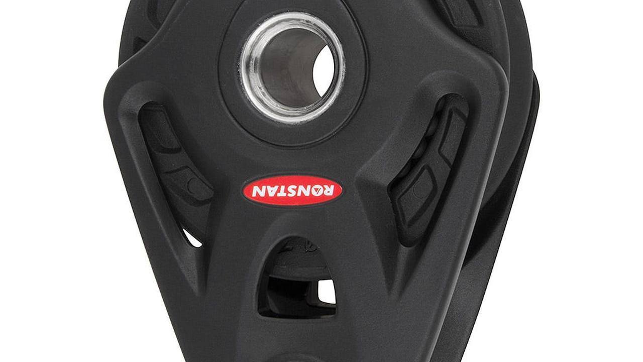
Bring the maneuver to the extremes of racing and repeat the check in the configurations that change the corner. The top should not touch cheeks, viteria, tree, tientibene or another bowl. Consider the volume of impiombatura and deformation when wet. The universal head must be oriented without overturning; a foot base must remain aligned. If the test requires you to drive the top with your hand, the layout is not ready: the defect will appear as soon as the crew will drop the branch.
Charge the system for increments
The test begins empty and continues with controlled levels, remaining very far from the nominal limit. After each increase download the circuit and inspect pin, grill, base, bolts, support and top. Apply visual references to the dice to detect rotations. A regular increase of effort is expected; shots, noises, laminate movement or lateral signs require arrest. No one should be on the trajectory of a top or a bozzello in case of failure.
Distingui attritus, misalignment and overload
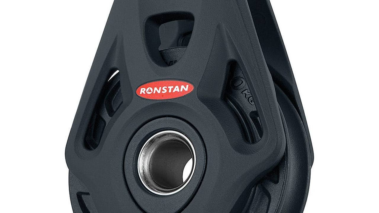
If the maneuver remains hard, download it and separate the causes. An empty rough pulley suggests contamination or damage; a vacuum fluid body but braked under fire can indicate oblique input, support of the pin or deformation of the base. A swollen top can be unsuitable to the throat. Do not increase the size before diagnosis. A 100 series mounted on the same incorrect path can transfer a greater load to an already insufficient blanket and make the fault more serious.
Record periodic control
Note code, date, location, top, head configuration, fixes and anomalies. Photograph cheek, pin and back of the base after assembly. After heavy outputs, shocks or exceptional loads anticipates inspection. Compare in the game time, marks on the bolts and wear of the throat. A simple register makes a gradual change visible and prevents the exchange of similar components between series. If you change sail, hoist or route, repeat the procedure from the start before using the boat.
Replace only with proven equivalence
A spare must meet load, pulley, top, attack, encumbrance and fixing. Do not transfer the single limit to the stand-up and do not adapt the foot strap. Keep pins and vices provided for the code; equal-looking elements can have different materials or classes. If there is no essential data, the maneuver remains out of service until verification. The equivalence is documented on the complete system: a larger draft is not equivalent when it compels the top to a new angle or the base to different holes.
The procedure closes with a repeatable test
The work is finished when a second operator can follow schema and register, recognize each component and repeat control. The top runs without manual guidance, the head takes the intended orientation, the base remains firm and each connection is visible. Critical measures are noted, not relied on memory. Series 75 and 100 offer high capacity, but safety is the result of the integration between the draft, maneuver and structure. If one of these three elements changes, validation must begin again.