
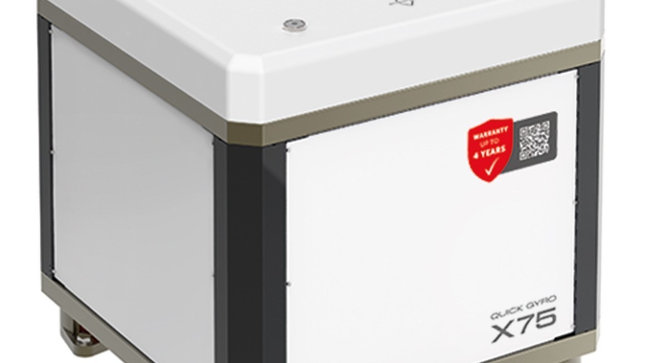
A stabilizer can look perfect during a demonstration and stay undersized, fed badly or integrated without a safe fault mode. The Quick MC2 range combines gyroscopes, Viator fins and interceptors with different models, couples, surfaces, power supplies, controls and modes. The technician must therefore verify identity, calculation, foundation or passage hull, energy, sensors, network, calibration and testing without transferring specifications from one product to another. This analysis builds a chain of evidence from the first inspection to the as-built file, keeping separate statements of the manufacturer, project hypothesis and measures of the ship delivered. The test must reproduce the load and the ranges for which the plant has been chosen, because an isolated demonstration does not close the requirements of cruise and stop. Instruments, system sensors and crew observations are synchronized but not confused, allowing to distinguish perceived comfort, measured movement and technical status. When the marine condition does not allow a representative verification, the minutes remain open with a new appointment instead of transforming the absence of data in conformity. The same discipline applies after any correction of software, sensors, appendices, foundation or distribution of the masses that may change the result.
Identify the complete configuration
The card records the family, model, quantity, serial, power, hardware, software, display, sensors, accessories and manual review. For multiple systems the role and address of each unit is indicated and the logic that coordinates them. Visually similar components are not united because torque, tension, implementation and compatibility can change. Each replacement generates a revision of the card before continuing with installation or calibration.
Relief and objective conditions
The relief includes operational displacement, mass distribution, famine forms, speed of use, spaces, structure, energy and interfering plants. The client describes sea, roll, berth, anchorage, cruise and activities that must improve. Measured data, yard documents and estimates are labeled separately so as not to give the same reliability to different information. The selection remains suspended when there is a variable capable of changing the model, quantity or position.
Check the sizing calculation
The document must identify boat, configuration, algorithm or method, hypothesis, model chosen and conditions for the expected performance. The range indicative length does not replace displacement, roll period, geometry and target of the single unit. For Quick Gyro it occurs to pair the model; for surface and position Viator; for Intercepta geometry and capacity of the expected series. Weight revisions or layouts reopen the calculation before laying.
Conformity matrix
Each requirement receives document, expected value, detected result, tool, responsible, date and outcome. The sections are structure, mechanical, sealing, electrical, cooling, control, network, calibration, testing and maintenance. A simple ignition does not close the conformity of a system that depends on movement, sensors and conditions of the sea. Critical anomalies suspend promotion to remedy and new evidence recorded.
| System | Project decision | Deciding verification |
|---|---|---|
| Gyroscope | Couple, weight, volume, power, cooling and foundation | Calculation applied to the boat and test under declared conditions |
| Pine | Surface, position, implementation, hull passage and protection | Installation, calibration, sealing and testing at various stages |
| Interceptor | Stern geometry, running, actuator, control and integration | Asset, response, symmetry and behaviour in virata |
| Control | Sensors, displays, network, modes and alarms | Autotest, degraded mode and test recording |
| Delivery | Schemes, manuals, maintenance, spare parts and warranty | As-built Paper and signed acceptance criteria |
Quick Gyro: model and foundation
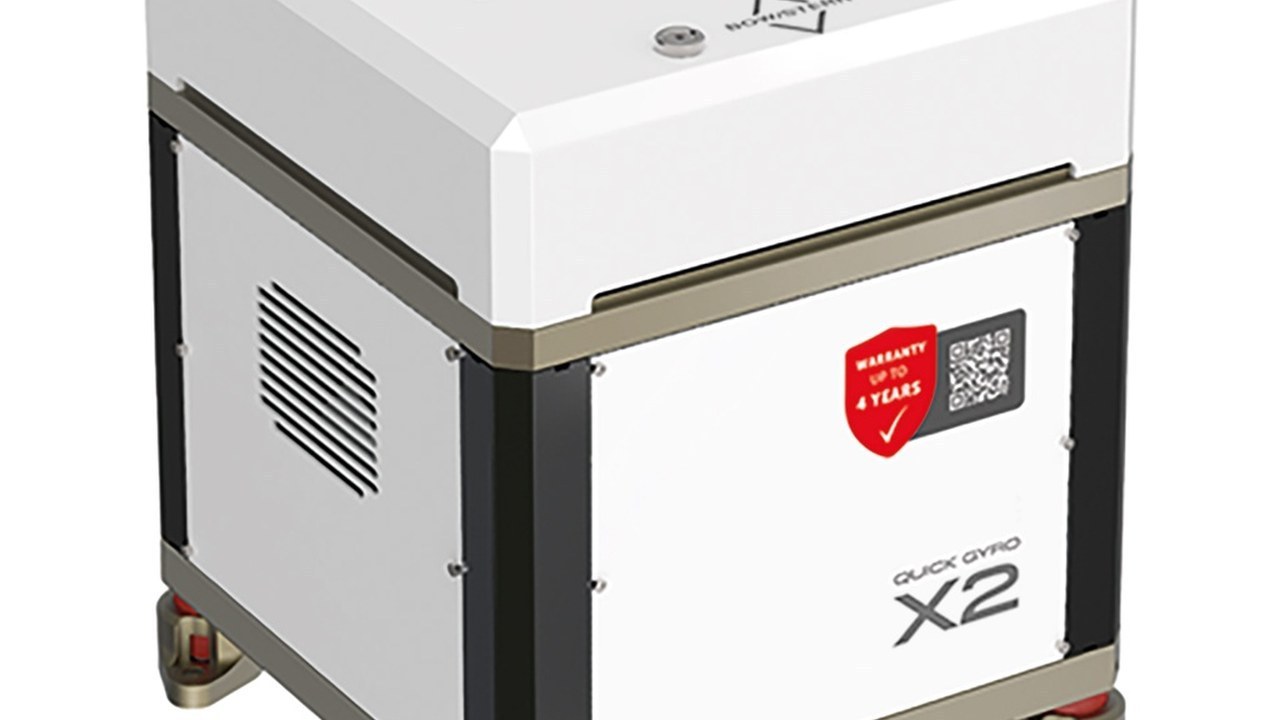
Code and tag are compared with the calculation and the DC or AC variant actually ordered. Foundation, support area, fixings, materials and load transfer follow the approved project. Position and orientation are measured before and after tightening, verifying safety spaces and absence of interference. Pictures and controls precede the closing of the compartment and preserve what will no longer be visible.
Movement and removal path
Weight, baricentre, lifting points and equipment are considered during boarding and positioning without improvisation. The technician checks doors, doors, doors, structures, furnishings and capacity of the lifting medium along the entire route. The future removal maintains a practicable space and outlet points accessible even after the completion of the interior. Each temporarily removed element is restored without closing inspections or ventilation.
DC or AC power supply
Scheme and tag set voltage, protections, sawing, conductors, conversion and possible load priority. Current, peaks, fall, temperature, path and laying enter the sizing and are verified in operation. Batteries, alternators, chargers, inverters or generators belong to the test when they really power the system. A provisional source cannot mask limits of the architecture delivered.
Ventilation, cooling and bilge
The compartment is checked for air inputs and outputs, temperatures, drainage, contamination and access to the points indicated by the manual. Condottes, fans or dedicated circuits are identified and tested under the most demanding conditions of the project. Water, vapours, obstructed filters and other nearby equipment are not excluded without inspection. Alarms and thermal protections are observed without forcing thresholds or deactivating security.
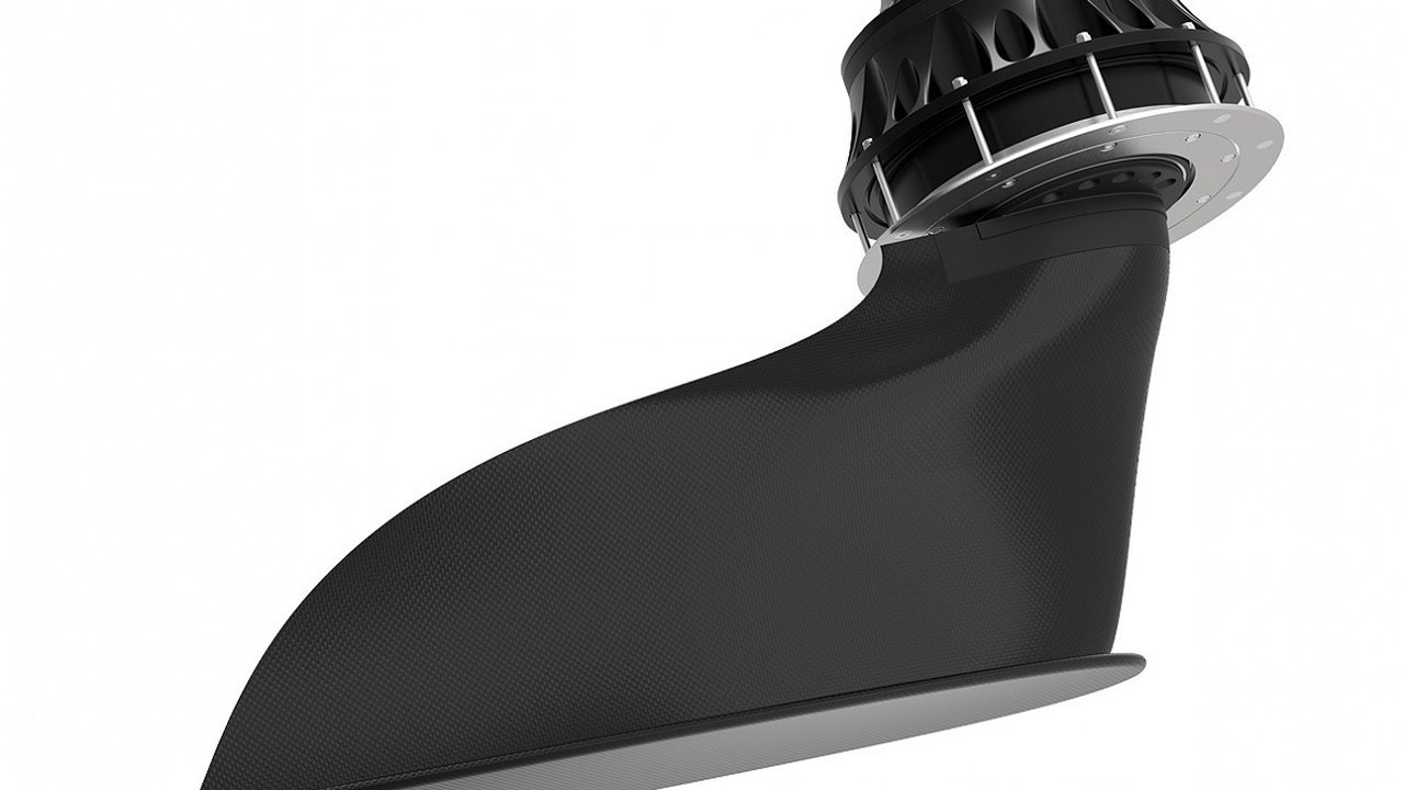
Viator: hull passage and structure
Model, surface, side and position of the fin must correspond to the calculation and approved drawings. Cutting, support, sealing, actuator and connections are documented for materials, quotas, fixings and controls performed. The outside area is verified compared to propellers, thymeans, sockets, skates, alge and possible shocks. Before the launch, protection, freedom of movement and internal access are confirmed.
Atuator, motor and safe position
Engines, reducers, control units and connections receive identity, locks and references consistent with the scheme. Race and rotation are only tested according to procedure, keeping people and tools out of the dangerous zone. The response to loss of power or communication is compared with the mode provided by the manufacturer. The position of the appendices must be known during fault, attachment, stop and maintenance.
Intercepta IN and X: do not confuse them
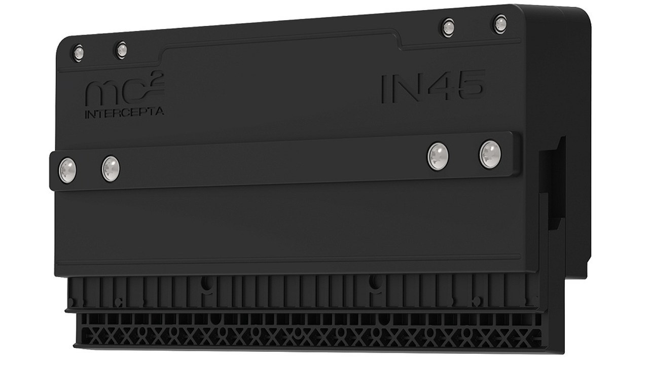
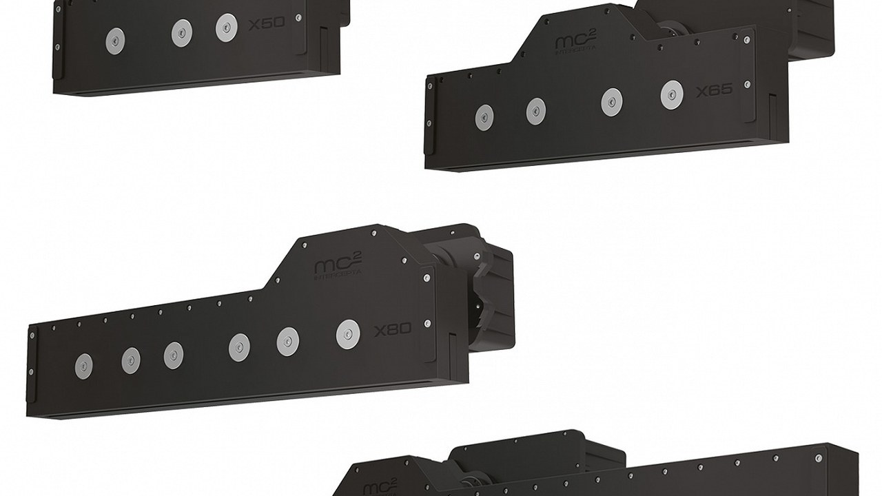
The official IN series integrates the electric actuator and includes distinct models, while the X allows customization with internal motor. the procedure keeps series, size, position, power supply, actuator and central unit without extending the laying from one family to another. Mirror, support, hold, run and access are verified before drilling or closing the area. The apparently simple installation remains an active system that depends on sensors and calibration.
Sensors and central units
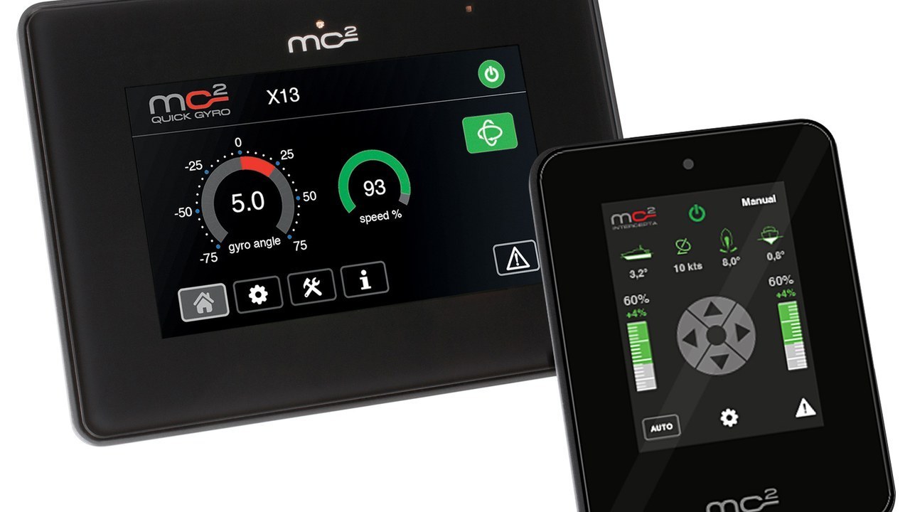
Position, orientation, fixing and reference of the sensors must correspond to the configuration procedure. Wiring and network are controlled for shielding, termination, power supply, identification and protection. The central unit must remain accessible and display version, status and diagnostics without dismantling. A replaced sensor requires new verification or calibration when expected, not the simple reset of the connector.
Display, QNN and Software
Remote panel, MC2 network and QNN integration are recorded for model, version, compatibility, addresses and enabled functions. The official list of compatible chartplotters refers to the device and the version actually installed. Try the local command and behavior when the integrated display, network or update are not available. Backups, credentials, configuration and recovery procedure enter the final file.
Fixed calibration
Identity, guidelines, sensors, end of stroke, communication, alarms and parameters required by the procedure occur before the exit. The boat is carried under the expected load and trim conditions, recording elements that can influence the reference. Default values are not accepted as calibrated only because the system does not report error. Any subsequent modification to relevant sensors, appendices or masses reopens the verification.
Try in navigation
The protocol establishes strokes, speed, route, sea, wind, load and modes to be compared before departure. Movement with system off and on is recorded when security and procedure allow it, avoiding comparisons on different waves presented as equivalent. System data, any independent instrument and crew observations remain synchronized. Cruise, low speed and turn only within the limits applicable to installed technology.
Try the anchor
For systems declared operating at anchor there are depth, freedom around the boat, wind, wave, drift and presence of people in water. The mode is activated and supervised according to manual, respecting limits of the appendices and procedures of the crew. Perceived comfort does not replace measurement, but helps to connect the result to the initial goal. A calm condition does not close the testing of a plant purchased for a different sea.
Alarms and degraded mode
There are loss of communication, unavailable source, protection intervention and simulable alarms in safety. The technician records message, system position, automatic action, available command and procedure for the crew. No security is excluded or bridged to complete the test. After restoration, logs, calibration and return to normal mode are checked before closing the result.
Maintenance and inspection
The plan distinguishes crew controls, periodic activities, updates, work in water and operations with winged boat. Foundations, fixings, ventilation, seals, hangers, actuators, cablings, sensors and software follow the installed model. Spare parts, tools and assistance are selected on the configuration and navigation area. Each intervention updates register and next test, keeping a useful history to diagnosis.
Paper and acceptance criteria
The file collects calculation, drawings, patterns, manuals, serials, software, photographs, calibration, measurements, maintenance and warranty. Acceptance criteria indicate agreed conditions, methods, thresholds or results and liability for any corrections. Provisional documents are replaced without losing the connection to the revision used during the work. The delivery takes place after a new test of the remedies and practical training of the crew.
Operating verdict
A stabilizer conforms when model, calculation, structure, energy, control and behavior belong to the same verified configuration. Quick Gyro, Viator and Intercepta require different diagnostic path in mechanical parts but share traceability, integration and testing. Maximum distances and range intervals remain indications of the manufacturer, not replaced of testing on the boat. The audit closes only when the result is repeatable and the file allows the crew and maintainer to manage the unavailableness.