
A thruster can work at the first touch and still be installed badly: insufficient tension, underwater tunnel, incorrect protection or impossible accesses often emerge only under load. The official Quick documentation separates DC, QSY, AC, DC-AC, hydraulic and retractable families and associates each specific power, power, thrust and diameter model. the technical procedure must therefore preserve the exact identity of the group and verify all the interfaces built around it. This procedure accompanies relief, installation, measurements, water proof and delivery without inventing performance that depend on the individual boat.
Open a unique tab
The first line records manufacturer, family, full model, voltage, power, declared thrust, tunnel, propeller, serial and manual revision. Visually similar components are not combined because contactors, drives, motors and accessories can change between versions. The card links photographs, measurements, drawings, calculations and minutes to the same unit and to the same date. Each replacement during the work generates an explicit revision of the dossier.
Relief before the quote
They measure the shape of the hull, accessible thicknesses, bulkheads, reservoirs, furnishings, wiring and volume necessary for motor or retractable mechanism. The odds include longitudinal position, height relative to the operating float, distance from the surfaces and access for mounting and removal. The relief signals un inspectable areas and tools used, avoiding reconstructed dimensions from photographs. Only after this step the installer can distinguish feasible solution, conditioned variant and proposed to be rejected.
Check the template table
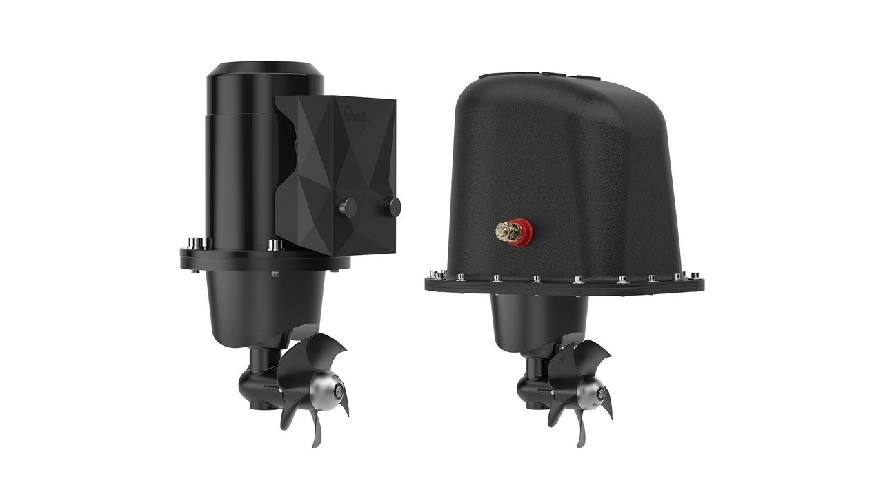
On the official DC page the BTQ 110-25 P is indicated at 12 volts, 1,300 watts, 25 kgf and 110 mm tunnel. The same family climbs through different diameters and configurations up to BTQ 300, with 24 or 48 volt power supply in the listed versions. Data is transcribed without moved commas, arbitrary conversions or associations between different lines. The range of boat length of the catalogue remains indicative and does not replace the sizing of the project.
Plant compliance matrix
Each item receives requirement, source, expected value, detected value, tolerance, responsible and outcome. The blocks are thrust, geometry, structure, power supply, command, protection, access, test and documentation. An unchecked field remains open and is not promoted to compliant because the component lights up. Critical non-compliance suspends testing or testing until documented remedy.
| Block | Date to be fixed | Deciding verification |
|---|---|---|
| Push | Model, voltage, power and declared thrust | Configuration and applicable conditions |
| Geometry | Tunnel, diving, location and structure | Quotated relief and installation project |
| Energy | Batteries, cables, protections and control | Clamp voltage during loading |
| Test | Direction, times, alarms and arrest | Dry and water minutes |
| Delivery | Manuals, schemes, spare parts and warranty | Issue reported to the real plant |
Tunnel and real location
Internal diameter, length, fittings, orientation and dive are compared with the instructions applicable to the model. The technician checks that the opening does not interfere with bulkheads, structures, plants or areas intended for the means of feeding. Simmetry and edge finishing are detected without automatically attributing a push defect to one cause. Before closing we document both faces and portions that will become invisible.
Structure and restoration
Materials, preparation, rolling or welding sequence, reinforcements and surface protection must belong to the project approved for hull. The control records environmental conditions, lots when expected, operators and checks performed before finishing. Removed panels and furnishings are restored without closing inspections, drains or escape routes. Waterproofness and continuity of anti-corrosion protection are confirmed before delivery.
Electrical architecture DC
The scheme identifies batteries, drive, protection, conductors, joints, power device, control and motor with real lengths. The section of the cable comes from current, path, allowed fall, temperature, laying and coordination of protection. Accessible connections receive controlled locking, environmental protection and marking consistent with the scheme. The negative is not treated as a generic return: path and connection points are part of the measure.
Battery and charging under examination
Technology, capacity, current available, charging status, temperature, fixing and ventilation are recorded for the bank that feeds the thruster. If there is a local battery, the charging circuit is tested under the conditions provided and coordinated with drive and protection. If the source is distant, the control considers the entire return and all intermediate connections. The test does not use a temporary external battery that masks the architecture delivered.
Measure voltage and current during the command
The voltage is measured at the terminals of the motor or at the point indicated by the procedure while the group operates in water, not only empty. Current, duration, charging status and temperature complete the data and allow to interpret the fall along the circuit. Instrument, scope, accuracy, position and now are noted in the minutes. An out threshold value leads to diagnosis on source, conductors, connections, protections and mechanical load without random replacements.
Protection and insulation
Fuse or switch must correspond to the project, stop the expected failure and coordinate with cable reach and manufacturer instructions. The insulation device must be accessible and clearly identified without exposing the operator to moving parts. Behaviour occurs after intervention, rehab or loss of the source, avoiding temporary bridges left on board. Labels and diagram indicate which part is possibly fed.
Fixed control and remote control
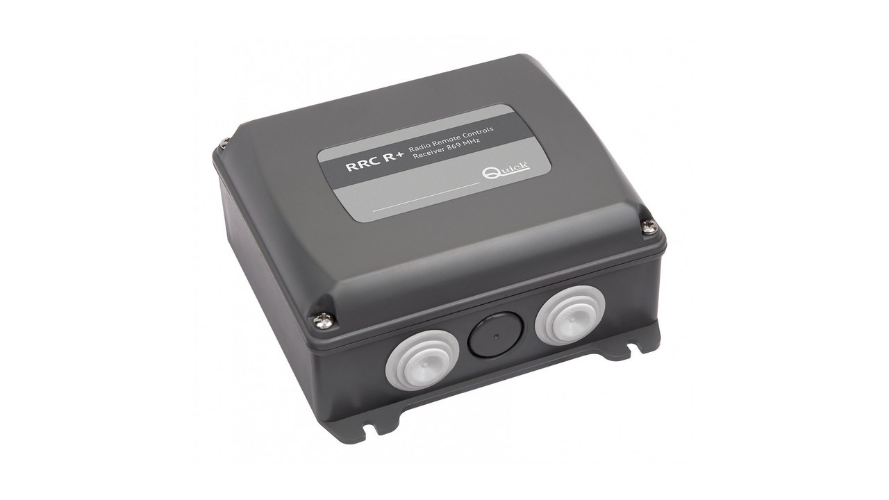
Each post is tested on the left and right, verifying correspondence between the indication, movement and response of the group. Consensus, delays, reports, timeouts and management of simultaneous commands are compared with the configuration manual. The official radio control is treated as an additional interface: pairing, battery, operational flow and signal loss enter the test. Delivery always maintains a controllable procedure even when the remote is not available.
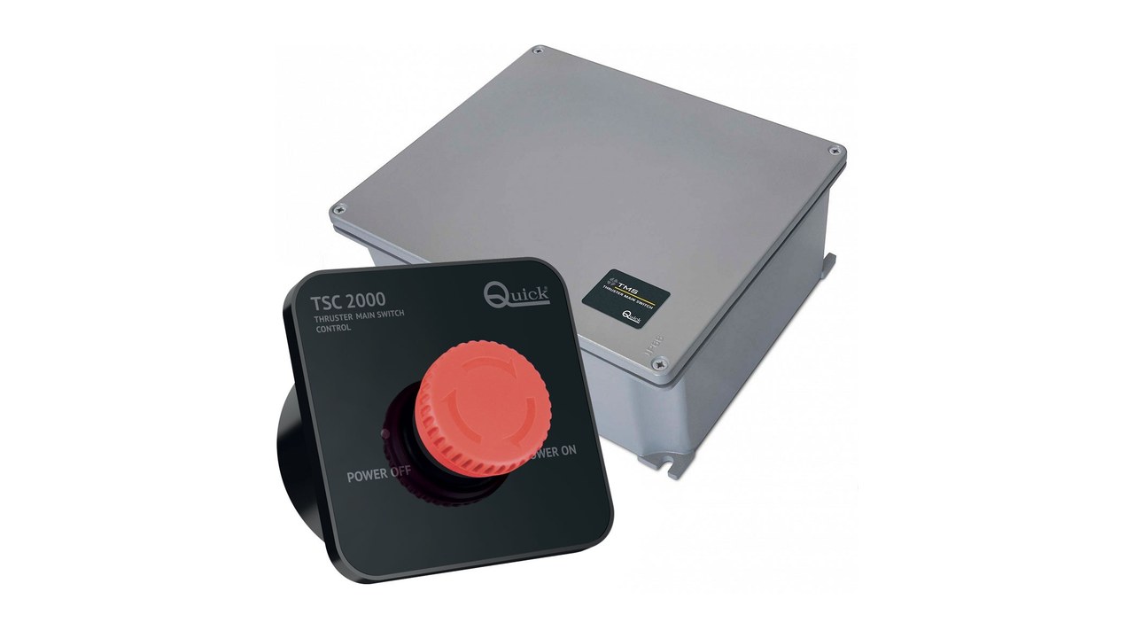
Retractable: Check the entire cycle
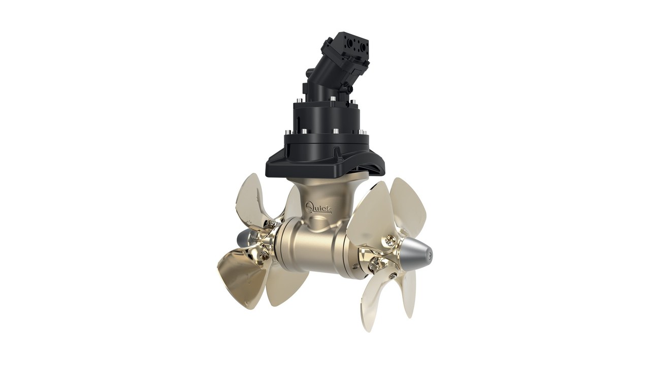
For a BTR or other retractable group it is not enough to verify the rotation of the propeller: opening, position, consent, operation, stop and return form only one sequence. Vano, drainage, seals, sensors, actuator, mobile parts and closing are inspected in accessible locations. They simulate power loss and interrupted command only according to safe procedure of the manufacturer. Any adjustment is recorded and reproduced before the launch or acceptance.
AC and DC-AC: dedicated checks
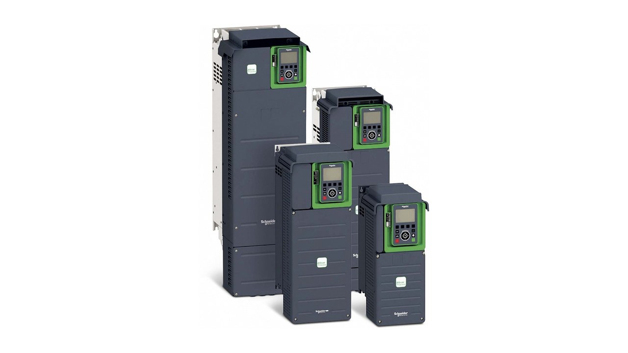
The official pages show AC systems at 400 or 690 volts and DC-AC families, so skills and protections cannot be borrowed from the small DC plant. Squares, conversion, insulation, grounding, cooling, interlocking and load priority require schemes and qualified personnel. Testing records network status, active sources and other loads while command is required. A functional test without these conditions does not show availability in real manoeuvres.
Hydraulic: pressure, flow and cleaning
A hydraulic system connects pump, tank, filtration, pipes, valves, motor and control; each interface can limit the performance. Pressure, flow, temperature and source conditions are measured at the points provided, with tools and values applicable to the project. Supports, curvature rays, rubbing protection, losses and maintenance access are controlled. Contamination or air in the circuit are not compensated by accidentally increasing times or pressure.
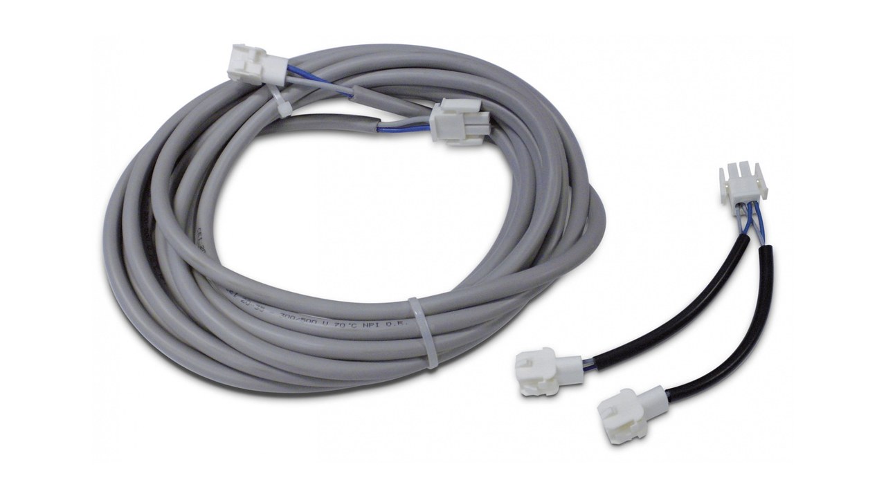
Dry test before varo
With free propeller and according to the limitations of the manual, the dry procedure checks identity, locks, insulation, continuity of controls and logic without imposing improper loads. Cinematism and sensors are controlled only under the conditions authorized by the manufacturer. They confirm direction, labels, stop and access to the section, recording each anomaly. Dry testing prepares the varo but does not replace measures and behaviour in water.
Water testing with recorded conditions
Before the command you control leaks, state of the bilge, tension or hydraulic circuit and freedom of openings. The tests on both sides use sequences and durations, with pause and monitoring required by the documentation. Wind, current, displacement, dive and famine status are noted to prevent uncontextual comparisons. Perceived thrust, noise and movement of the boat integrate but do not replace the instrumental parameters.
Fault scenarios and degraded modes
The technician checks the loss of control, protection intervention, low voltage, alarm, failure to return or unavailable source within the limits of a safe test. The crew must know when to stop the attempts and return to main propulsion, peaks, wind and external assistance. The procedure avoids access to propellers or mobile parts until fuels and residual energies are isolated. Each scenario produces concrete action, not a generic invitation to consult the manual.
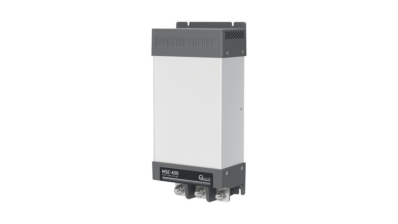
Noise, vibration and basic diagnosis
An initial reference is recorded with boat, position, voltage, duration and known conditions, so future variations become observable. Irregular noise may depend on flow, fouling, propeller, fixing, structure or power and does not receive a cause without verification. After the installation, openings, propellers, game and second manual damage are inspected, while on board you control locks and connections. The diagnosis proceeds from the simplest and safest data to the authorized disassembly.
Maintenance and spare parts
The calendar distinguishes inspections before departure, periodic checks, seasonal activities and work with boat out of water. Fouling, anodes if provided, propeller, tunnels, seals, electrical or hydraulic components and retractable mechanism follow the model documentation. Spare parts and tools are chosen according to the possibility of intervention of the crew and availability in the navigation area. Each intervention updates date, hours or cycles when available and result of the next test.
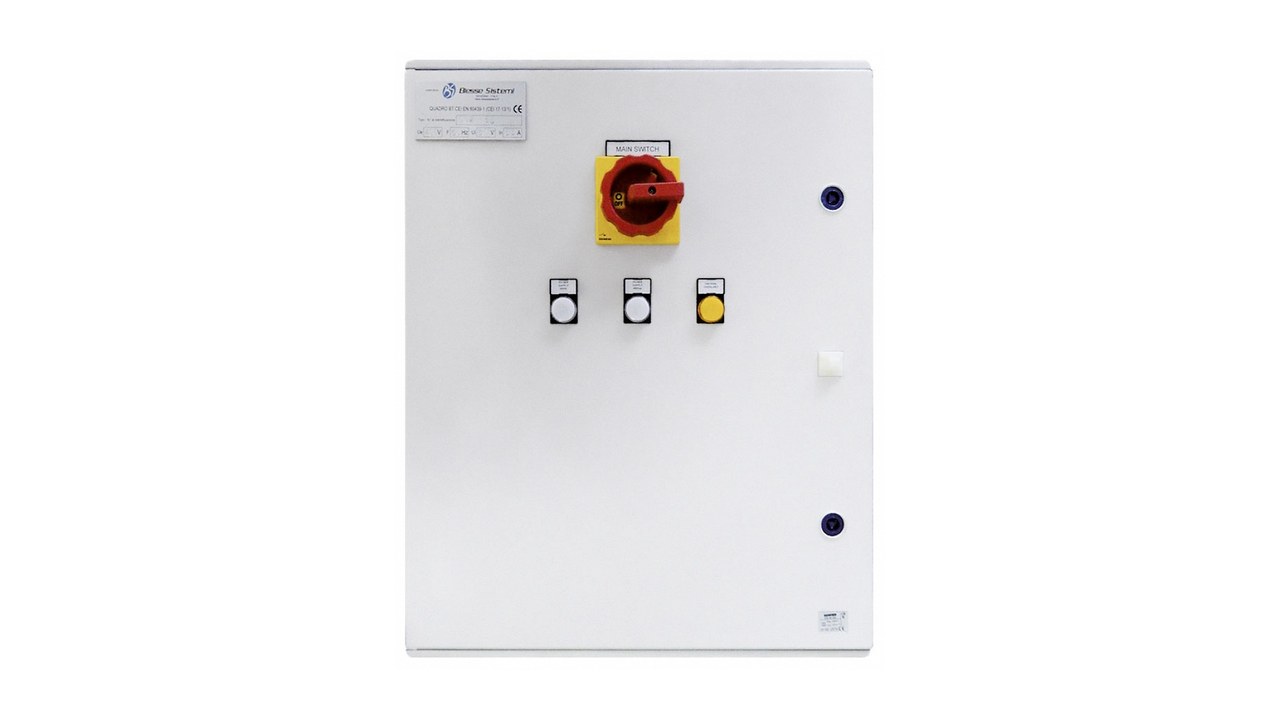
Paper and acceptance criteria
Delivery includes manuals, planned statements, drawings, diagrams, calculations, hidden photographs, measures, minutes, maintenance and warranty. The contract defines correct direction, absence of losses, electrical or hydraulic values acceptable, operation of alarms and closure of defects. Installer and supplement indicate their respective responsibilities without leaving open interfaces. Acceptance occurs only after new proof of corrections and delivery of the final revision of documents.
Operating verdict
The reliable thruster is not the one that turns to the counter, but the one identified, dimensioned, installed and measured in the boat to which it belongs. Quick families demonstrate the width of variants and prevent using a generic specification as a substitute for the real model. Relief, voltage or hydraulic parameters under load, logic, retractable cycle and documents are the steps that avoid failures to the first challenging mooring. the procedure closes every evidence before turning a successful test into technical acceptance.