
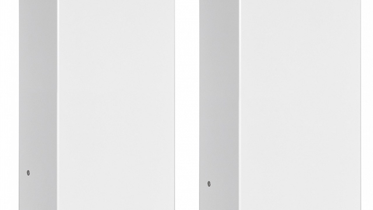
Un caricabatterie che mostra una spia verde può nascondere un banco non identificato, una caduta sui cavi o un sensore termico associato alla batteria sbagliata. La verifica degli SBC NRG+ Quick deve collegare modello, ingresso AC, uscite DC, chimica, protezioni, ventilazione, accessori CAN e misure sui morsetti reali. La gamma dichiara carica IUoU a tre stadi, uscite multiple, profili differenziati ed efficienza fino al 92 per cento, dati che vanno mantenuti insieme alla famiglia e alle condizioni ufficiali. questa analisi segue energia, informazioni e temperatura dalla sorgente ai banchi e chiude il lavoro soltanto con un ciclo osservato e un fascicolo as-built. Prima di scollegare si esegue un rilievo fotografico e strumentale dell’impianto esistente, includendo commutatori, ritorni, ponti, caricatori paralleli e utenze che potrebbero mantenere tensione sui conduttori. Il piano di prova stabilisce strumenti, tolleranze, punti di misura, stato iniziale delle batterie, carichi attivi, sorgente AC, durata e criteri di arresto prima che l’apparecchio venga energizzato. Tensione a vuoto, tensione sotto carico e valore mostrato dal pannello vengono conservati come grandezze diverse, perché la loro apparente somiglianza non dimostra che sensori e cablaggi leggano lo stesso punto. La temperatura viene rilevata sul banco, nel vano e sull’apparecchio nei punti autorizzati, evitando di attribuire al caricabatterie il calore prodotto da inverter, generatori o batterie difettose vicine. Quando un’anomalia richiede una correzione, il tecnico ripete tutte le prove influenzate e non soltanto quella fallita, dato che una nuova sezione di cavo o un parametro diverso può modificare distribuzione e transizioni. Il fascicolo finale conserva configurazione, password o accessi assegnati, versioni, seriali e backup necessari per ripristinare display e rete senza cambiare involontariamente il profilo dei banchi. L’addestramento mostra isolamento, riconoscimento degli allarmi e controlli consentiti all’equipaggio, separando chiaramente le attività operative dagli interventi riservati a personale qualificato. Prima della consegna si esegue anche un controllo incrociato fra schema, etichette e collegamenti fisici, seguendo ogni uscita fino al banco per eliminare inversioni o nomi ereditati da vecchie configurazioni. Il tecnico registra lo stato delle batterie prima e dopo la prova con lo stesso metodo, evitando che un recupero apparente venga attribuito al caricabatterie quando deriva dalla rimozione temporanea di un carico importante. Le soglie di arresto del protocollo comprendono temperatura anomala, odore, rigonfiamento, rumore, instabilità della sorgente e riscaldamento dei terminali, condizioni che impongono isolamento e diagnosi prima di continuare. Quando più sorgenti possono caricare lo stesso banco, alternatore, solare e apparecchi paralleli vengono esclusi o misurati secondo il piano, così la corrente osservata mantiene una provenienza dimostrabile. Il carico dei servizi viene misurato o stabilizzato durante ogni lettura, evitando che l’avvio casuale di una pompa o di un frigorifero venga scambiato per una variazione della corrente destinata al banco. Su impianti a più uscite si verifica inoltre la continuità e la corretta polarità di ciascun ramo prima del collegamento definitivo, mantenendo le batterie isolate secondo la procedura di sicurezza. La prova del generatore include avviamento degli altri carichi autorizzati e osservazione della tensione di ingresso, senza forzare il sistema oltre la potenza continua dichiarata dalla sorgente. Dopo la chiusura dei pannelli si ripete una breve verifica termica e funzionale, perché cablaggi spostati, griglie parzialmente coperte o accessi ridotti possono cambiare rispetto alla prova a vano aperto. Infine il verbale indica esplicitamente ciò che non è stato provato, le condizioni necessarie per completarlo e il responsabile della successiva verifica, impedendo che un limite operativo scompaia nella consegna.
Inventario con targhette e schemi
Si registrano caricabatterie, banchi, batterie, separatori, inverter, sensori, display, gateway, protezioni e sorgenti. Codice, seriale, tensione, corrente e revisione del manuale vengono fotografati e confrontati con l’ordine. I collegamenti esistenti vengono rilevati prima di scollegare, distinguendo documenti affidabili da ipotesi. Ogni variante scoperta aggiorna schema e piano di prova.
Identità dei banchi
Per ogni banco si annotano funzione, tensione, chimica dichiarata, capacità, numero di elementi, età e stato osservato. Collegamenti serie e parallelo vengono verificati fisicamente e non dedotti dalla tensione a riposo. Batterie differenti o sostituite parzialmente vengono segnalate prima di configurare il profilo. La destinazione di ogni uscita è etichettata ai due estremi.
Confermare modello e prestazioni
Mini/Low, Medium e Hi Power comprendono codici a 12 e 24 V con correnti diverse. La targhetta deve coincidere con progetto, ingresso disponibile, uscite e profilo dei banchi. Funzioni come accessori remoti o sensori vengono confermate sulla compatibilità del codice, non sulla famiglia generica. Il tecnico conserva la tabella ufficiale usata per l’accettazione.
Matrice di prova
Ogni requisito riceve punto di misura, strumento, condizione, valore atteso, risultato, data e responsabile. Le aree sono AC, DC, banchi, temperatura, ventilazione, rete, protezioni, allarmi e modalità degradata. Un campo non provato resta aperto e non viene chiuso con una spunta priva di evidenza. Dopo un rimedio si ripetono le misure influenzate.
| Blocco | Decisione | Prova conclusiva |
|---|---|---|
| Banchi | Chimica, tensione, capacità, priorità e separazione | Identità e misure a riposo e in carica |
| Caricabatterie | Modello, corrente, uscite, profilo e sorgente AC | Ciclo osservato con carichi rappresentativi |
| Distribuzione | Protezione, sezionamento, conduttori e caduta | Tensione, corrente e temperatura ai punti definiti |
| Monitoraggio | Sensori, display, rete, allarmi e versioni | Valori confrontati con strumenti indipendenti |
| Consegna | Schemi, settaggi, manuali e modalità degradata | Fascicolo as-built e addestramento |
Ingresso AC e terra
Si controllano sorgente, commutazione, protezione, conduttori, terra e polarità secondo impianto e manuale. Tensione e frequenza vengono rilevate a vuoto e durante carica rappresentativa. Generatore e banchina vengono provati separatamente quando entrambi sono autorizzati. Cadute o distorsioni non vengono attribuite al caricabatterie senza misure sulla sorgente.
Montaggio e ventilazione
Posizione, orientamento, distanze, fissaggi e accesso all’aria seguono la documentazione del modello. Il vano viene ispezionato per acqua, sale, vapori, polvere, ricircolo caldo e apparecchi vicini. La ventola a velocità variabile viene osservata senza bloccarla o coprire le griglie. La temperatura viene registrata in punti definiti per una durata significativa.
Protezione dei circuiti DC
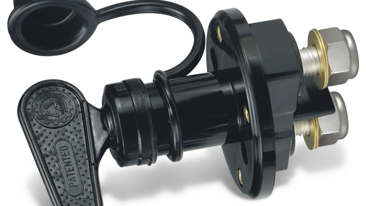
Fusibili integrati e dispositivi dell’impianto vengono identificati con funzioni separate. Ogni uscita segue un percorso protetto e sezionabile coerente con conduttore e banco. I collegamenti restano inaccessibili a contatti accidentali ma praticabili per ispezione. La prova di isolamento operativo evita ritorni da altri caricatori o alternatori.
Sezioni, terminali e caduta
Lunghezza, sezione, posa, temperatura e corrente prevista vengono confrontate con il progetto. Crimpature, serraggi, ossidazione e supporti vengono controllati prima di energizzare. Sotto carico si misura la differenza fra uscita del caricabatterie e morsetti della batteria. Un terminale caldo impone arresto e diagnosi, non un serraggio casuale a circuito attivo.
Impostare la chimica corretta
La configurazione viene confrontata con scheda del banco per elettrolita liquido, gel, AGM o altra opzione esplicitamente supportata. Valori e sequenza provengono dal manuale della revisione installata. L’impostazione viene registrata prima e dopo il collaudo per rilevare modifiche involontarie. Banchi incompatibili non vengono forzati sulla stessa uscita per completare il lavoro.
Sensori KTBS e interfaccia KTB4
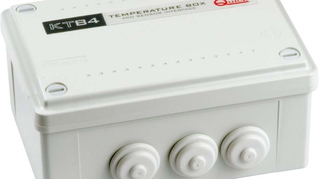
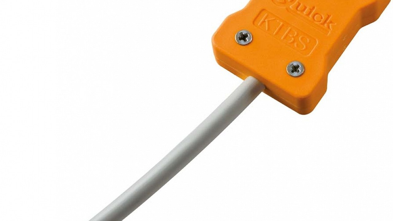
Ogni sensore viene associato al banco, fissato nel punto previsto e protetto da trazione o sorgenti termiche estranee. KTB4 può leggere più sensori e comunicare via CAN nelle configurazioni dichiarate, ma indirizzi e compatibilità vanno documentati. Le temperature visualizzate vengono confrontate con uno strumento indipendente in condizioni stabili. Scollegamento o valore implausibile devono produrre il comportamento previsto dal sistema.
Uscite multiple e sbilanciamento
Si misurano tensione e corrente di ogni uscita con banchi in stati differenti e carichi registrati. La corrente totale del caricabatterie non viene interpretata come corrente identica su ciascun ramo. Un banco molto scarico o degradato viene diagnosticato senza mascherare gli altri risultati. Separazioni e ritorni vengono confermati con schema e misure controllate.
RDS 1562 e CAN bus
Sul Medium o Hi Power compatibile si verificano alimentazione, CAN, terminazioni, versione e parametri del pannello RDS 1562. Le tre tensioni mostrate e la corrente totale vengono confrontate con punti di misura definiti. Buzzer, contrasto e impostazioni non sostituiscono la verifica degli allarmi reali. Una perdita di comunicazione non deve rendere impossibile isolare o diagnosticare il caricabatterie.
Integrazione QNN
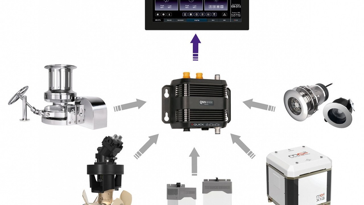
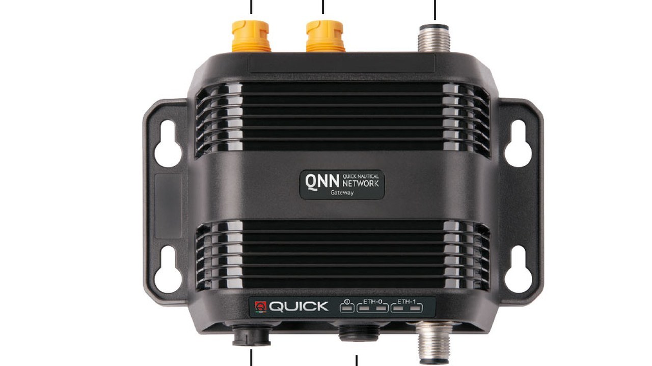
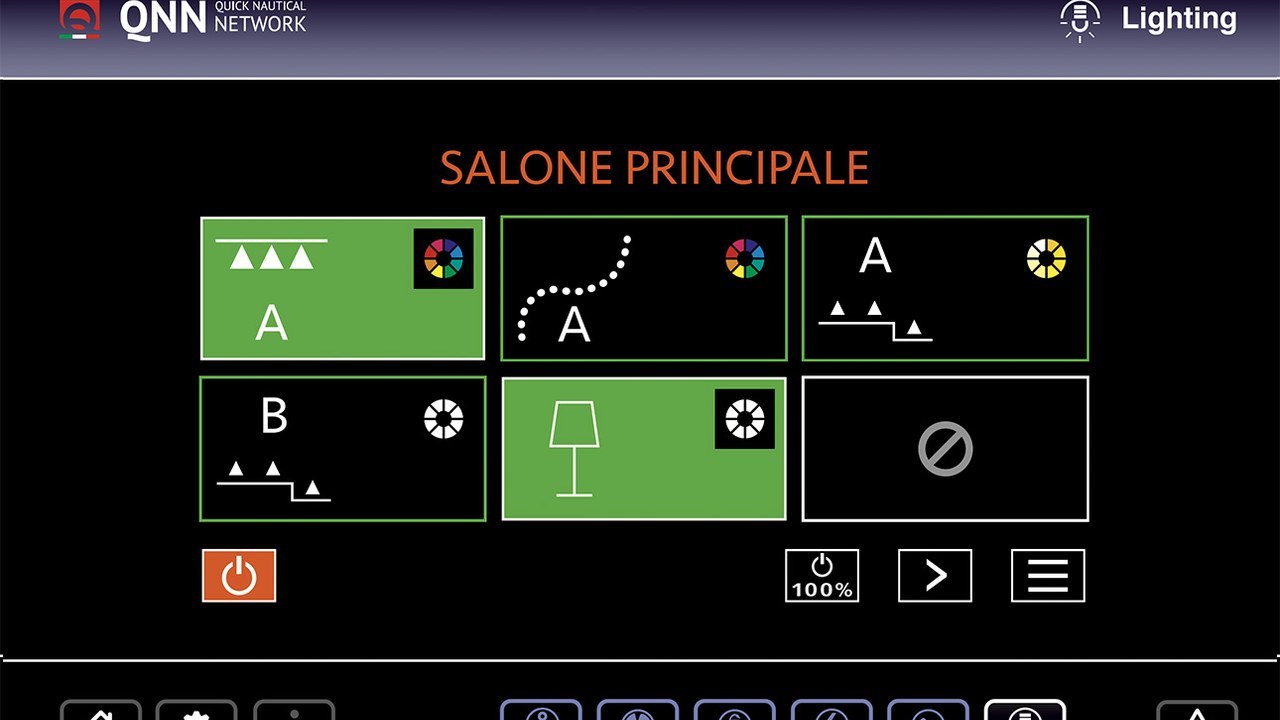
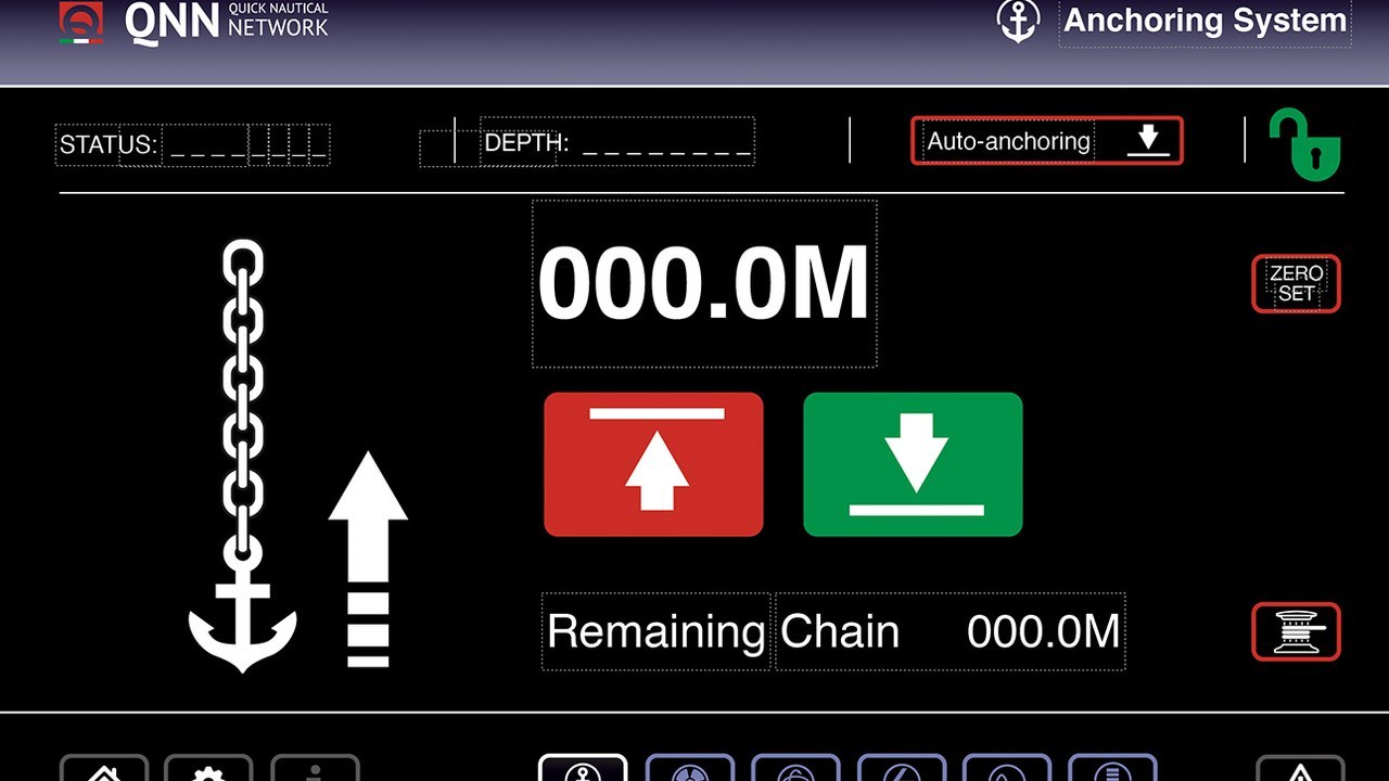
Gateway, chartplotter e caricabatterie vengono registrati con modello, versione e compatibilità ufficiale. Stato e comandi disponibili sono provati senza presumere che ogni funzione locale sia replicata. Si spegne il display integrato secondo procedura per verificare la gestione locale e il recupero della rete. Backup e configurazione vengono consegnati prima di aggiornamenti software.
Separatore ECS
Codice, numero di uscite e corrente del separatore vengono confrontati con schema e sorgente. La tecnologia MOSFET dichiarata riduce la caduta rispetto a dispositivi tradizionali, ma collegamenti e dissipazione restano da misurare. Ogni ramo viene provato per distribuzione e isolamento del banco. Un guasto di batteria non deve essere confuso con un difetto del separatore senza evidenza.
Inverter e commutazioni
L’inverter HSI viene trattato come sorgente AC separata con protezioni, carichi e display propri. Si verifica che il caricabatterie non venga alimentato in un ciclo non previsto dall’energia dello stesso banco. Commutazioni fra banchina, generatore e inverter seguono interblocchi e priorità documentati. Ogni modalità viene provata con carichi autorizzati e misure su ingresso e uscita.
Ciclo di carica documentato
Il verbale parte da stato iniziale, temperatura e carichi e registra tensione e corrente a intervalli coerenti. Le transizioni IUoU vengono riconosciute secondo manuale e non soltanto dal tempo trascorso. Il collaudo dura abbastanza da osservare comportamento termico e distribuzione senza oltrepassare limiti. Un banco già pieno non è una prova rappresentativa della fase a corrente elevata.
Allarmi e modalità degradata
Si verificano segnalazioni disponibili per sovraccarico, sovratemperatura, sovratensione e anomalie simulabili senza rischio. Nessuna protezione viene ponticellata e nessun corto viene creato per dimostrare una funzione. La perdita di sensore, pannello o rete viene gestita secondo procedura del modello. Dopo il ripristino si controllano log, parametri e ritorno alla carica normale.
Fascicolo e consegna
Il fascicolo raccoglie schema AC/DC, targhette, manuali, profili, sensori, rete, fotografie e tutte le misure. Si consegnano posizione delle protezioni, isolamento, priorità delle sorgenti e risposta agli allarmi. L’equipaggio esegue una prova pratica senza intervenire su parti energizzate. Modifiche future a batterie o sorgenti riaprono configurazione e collaudo.
Verdetto operativo
L’impianto è accettabile quando banchi, profili, sorgente, cavi, temperatura e monitoraggio raccontano la stessa configurazione. Una spia verde non sostituisce tensioni, correnti e temperature misurate nel tempo. SBC NRG+, accessori e QNN offrono funzioni precise soltanto sulle combinazioni compatibili documentate. la procedura si chiude quando anche la modalità degradata resta comprensibile e sicura.