

Quando una pompa, una luce o un attuatore non risponde sul display YachtSense, il guasto può trovarsi nel carico, nel cablaggio, nel fusibile, nel canale, nella pila dei moduli, nella rete o nella configurazione. Cambiare il modulo senza una sequenza di prove rischia di spostare il problema e cancellare indizi utili. La diagnosi corretta parte dal comportamento osservato, identifica il circuito sulla matrice e verifica prima energia e sicurezza. Solo dopo separa comando, uscita e feedback, usando modalità minima e bypass esclusivamente come previsto e senza trasformarli in riparazioni permanenti.
Registra il sintomo prima di toccare l’impianto
Annota quale servizio manca, da quale pagina, su quali display, in quale stato della barca e se il difetto è continuo. Verifica se il comando cambia aspetto, se compare un allarme e se il carico emette rumore o movimento. Fotografa schermata, pila e posizione dei cablaggi. Non riavviare subito tutto: un riavvio può ripristinare temporaneamente la funzione senza indicarne la causa. Confronta il nome visualizzato con la matrice dei canali; se il documento manca o non è aggiornato, fermati prima di ponticellare o spostare connessioni non identificate.
La tabella impedisce diagnosi circolari
| Sintomo | Prima verifica | Direzione successiva |
|---|---|---|
| Un carico offline | Canale, fusibile e uscita | Carico o tratta |
| Più carichi offline | Modulo e alimentazione comune | Pila o distribuzione |
| Comando assente | Pagina e configurazione | Master o rete |
| Valore errato | Misura indipendente | Sensore o scala |
| Una direzione assente | Modulo inversione e limiti | Attuatore o interblocco |
| Guasto intermittente | Carico simultaneo e calore | Caduta o ambiente |
Un solo carico orienta verso il suo ramo
Se tutti gli altri servizi dello stesso modulo funzionano, controlla il canale specifico, la protezione, il connettore, il cavo e l’utenza. Se più canali dello stesso modulo sono assenti, il punto comune diventa più probabile. Se più moduli smettono insieme, risali ad alimentazione della pila, master o rete. Questa logica per insiemi riduce rapidamente il campo. Non presumere però che due carichi abbiano la stessa alimentazione soltanto perché compaiono sulla stessa pagina: l’interfaccia è una vista operativa, mentre la matrice elettrica mostra la reale dipendenza.
Controlla la pila senza smontarla a tentativi
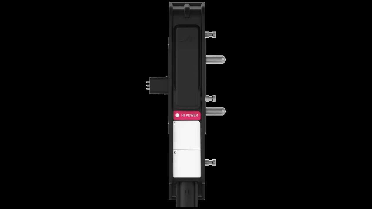
Osserva master, alimentazione e moduli, registrando indicatori e messaggi prima e dopo un riavvio ordinato. Verifica che connettori e barre siano inseriti, protetti e privi di calore, scolorimento o umidità. Non estrarre moduli sotto carico se la procedura non lo consente. Un serraggio difettoso può causare cadute intermittenti quando partono pompe o frigoriferi. Se la pila è inaccessibile o il fascio esercita trazione, documenta il difetto installativo. La diagnosi deve proteggere prima le persone e i circuiti, poi ripristinare il servizio.
Misura l’alimentazione nel momento critico
La tensione a vuoto può sembrare corretta e crollare all’avvio del carico. Misura sul punto previsto della pila e, quando sicuro, sul carico, registrando riposo, comando e regime. Controlla protezione a monte, portafusibile, ritorno negativo e connessioni. Se il difetto compare con più utenze attive, ripeti la prova nelle stesse condizioni. Non aumentare il valore del fusibile per impedire l’apertura: la protezione è dimensionata insieme a conduttore e carico. Un intervento che elimina il sintomo sovradimensionando la protezione crea un rischio più grave del guasto iniziale.
Il modulo a bassa potenza richiede il carico giusto
Il modulo dedicato offre quattro canali da 10 A per utenze compatibili come luci o tergicristalli. Verifica che il circuito sia realmente assegnato a quel modulo e che corrente nominale e di spunto rientrino nel progetto. Un motore bloccato può assorbire più del normale e far intervenire la protezione del canale. Isola il carico secondo la procedura e prova la parte meccanica separatamente, senza collegarla a una sorgente improvvisata. Se il difetto segue l’utenza, il modulo può essere sano; se resta sul canale con un carico campione approvato, approfondisci l’uscita.
L’alta potenza si verifica durante lo spunto
I due canali da 20 A del modulo ad alta potenza servono carichi più impegnativi, ma pompe, ventilatori, riscaldatori e frigoriferi possono avere avvii differenti. Registra tensione e comportamento quando il dispositivo parte. Un compressore che tenta più volte di avviarsi può indicare caduta, blocco meccanico o protezione, non un comando digitale errato. Controlla se il carico funziona nelle condizioni previste con una procedura autorizzata, preservando fusibili e cablaggio. Non sostituire il modulo finché non hai escluso un assorbimento anomalo dell’utenza.
Il modulo reversibile va provato nelle due direzioni
Per tetti, tende, finestre o attuatori, annota se manca una sola direzione o entrambe. Una direzione assente può dipendere da limite, interblocco, collegamento o parte meccanica. Non insistere sul comando contro un fine corsa e non bypassare sensori di sicurezza per “vedere se parte”. Verifica corrente, cablaggio e stato logico in apertura e chiusura. Il modulo controlla un circuito DC con inversione di polarità: confondere i conduttori o simulare il comando con ponticelli casuali può provocare movimento inatteso. Mantieni libera l’area dell’attuatore durante ogni prova.
Un dato plausibile può essere comunque sbagliato
Il modulo segnali accetta fino a quattro ingressi per livelli, tensioni, temperature, interruttori o sensori compatibili. Confronta il valore mostrato con una misura indipendente in almeno due condizioni. Un serbatoio che resta al 60 per cento può avere sensore bloccato, scala errata o circuito aperto interpretato male. Controlla tipo di ingresso, alimentazione del sensore, massa di riferimento e cablaggio. Se un canale è usato come uscita a bassa corrente, non trattarlo come ingresso. La configurazione deve corrispondere alla funzione fisica e alla relativa unità.
Se manca il comando, separa display e master
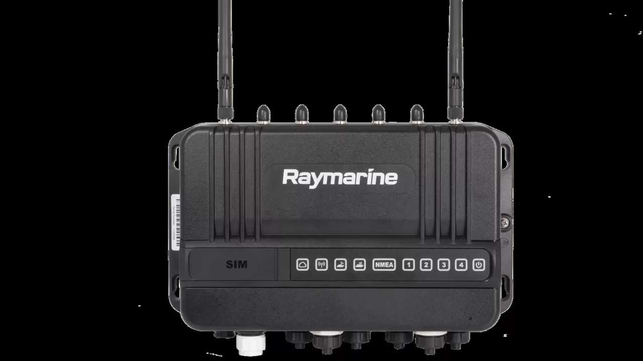
Quando la pagina non appare o nessun comando raggiunge i moduli, verifica prima se il master conserva il controllo locale. Tastiera e LCD sono previsti per la modalità minima durante un’interruzione di rete. Se il servizio è disponibile localmente ma non sul display, il ramo elettrico può essere sano e l’attenzione passa a rete, pagina e configurazione. Se non è disponibile neppure localmente, controlla master, alimentazione e stato dei moduli. Non confondere una pagina personalizzata mancante con un’uscita guasta: sono livelli diagnostici differenti.
La modalità minima è una prova controllata
La perdita di rete deve essere simulata soltanto seguendo la procedura dell’installazione. Prima identifica i servizi che devono restare accessibili e prepara il ripristino. Durante la prova verifica che i moduli continuino a operare come previsto e che tastiera e LCD del master offrano il controllo minimo configurato. Un esito diverso va registrato senza improvvisare una nuova logica sul posto. La modalità minima non garantisce automaticamente ogni comfort: il progetto decide quali funzioni hanno priorità. L’equipaggio deve conoscere questa selezione e saper raggiungere il master.
Il bypass manuale non deve nascondere il guasto
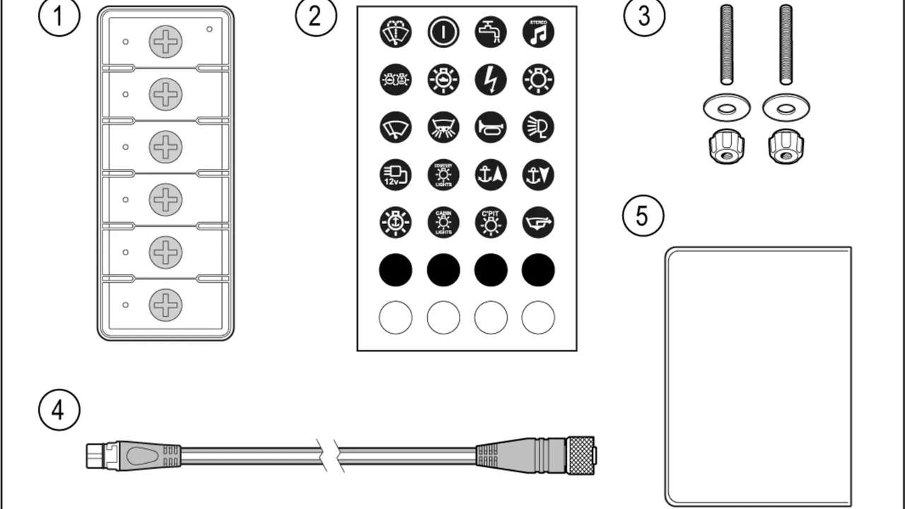
Il bypass del fusibile è descritto come override temporaneo in caso di guasto di modulo. Prima di usarlo verifica circuito, carico e rischi, quindi applica la procedura autorizzata. Sorveglia il servizio e rimuovi il bypass appena conclusa la necessità. Se l’utenza funziona in bypass, hai un’indicazione utile ma non una diagnosi completa: restano da distinguere modulo, protezione, comando e cablaggio. Non lasciare la barca con un override non registrato. Dopo l’intervento ripristina tutte le protezioni e aggiorna il rapporto tecnico.
Gli allarmi vanno letti insieme alle misure
Un allarme di livello, tensione o temperatura deriva da sensore, scala, soglia e logica. Prima di modificarlo, confronta il valore con uno strumento indipendente e controlla se la condizione è reale. Silenziare un allarme ripetitivo non corregge un sensore difettoso; alzare la soglia può nascondere un rischio. Registra momento, carichi attivi e stato della barca. Se l’allarme appare solo durante l’avvio di un’utenza, indaga caduta o disturbo. Dopo la correzione forza una condizione controllata e verifica comparsa, riconoscimento e ripristino del messaggio.

Il calore e l’umidità creano difetti intermittenti
Gli involucri IPX6 proteggono i moduli, ma un vano caldo, saturo o con connessioni bagnate resta problematico. Controlla ventilazione, spruzzi, condensa, fissaggi e materiale stivato attorno alla pila. Un sistema che funziona a freddo e cede dopo ore va provato con i pannelli nella posizione normale e i carichi reali attivi. Non asciugare semplicemente la superficie senza trovare l’ingresso d’acqua. Verifica connettori sigillati, guarnizioni e crimpature. La correzione può richiedere riposizionamento o protezione del vano, non un nuovo modulo.
La configurazione si modifica soltanto dopo il fisico
Prima salva la configurazione approvata e registra versioni e pagine. Un aggiornamento o una nuova assegnazione di canale cambia molte variabili e può rendere irripetibile il guasto. Dopo avere verificato alimentazione, modulo, uscita, carico e rete, confronta la funzione digitale con la matrice. Controlla nome, tipo di canale, logica, soglie, consenso e feedback. Se serve una modifica, eseguila con chi ha la competenza di sistema e conserva una copia precedente. Ripeti tutte le prove pertinenti: una pagina corretta non dimostra che protezioni e modalità minima siano rimaste coerenti.

Una prova sotto carico chiude il cerchio
Riattiva progressivamente le utenze e riproduci lo scenario in cui il difetto appariva. Osserva tensione della pila, stato dei canali, temperatura e feedback. Prova combinazioni realistiche, non tutte le utenze a caso, e ripeti dopo un ciclo completo di spegnimento. Se il problema emerge solo con più carichi, torna a distribuzione, sezione, connessioni e dissipazione. Se resta associato allo stesso canale con un carico verificato, il modulo diventa un sospetto concreto. Ogni sostituzione deve essere seguita dallo stesso test, altrimenti manca il confronto.
Il ripristino comprende cablaggio e documenti
Rimonta protezioni e connettori, elimina cavi di prova, sostiene i fasci e chiude il vano. Verifica tutti i servizi, non soltanto quello riparato, perché durante la diagnosi potrebbero essere stati scollegati altri rami. Aggiorna matrice, schema, configurazione, fotografie, misure e componente sostituito. Registra eventuale uso del bypass e conferma che sia stato rimosso. Consegna all’armatore una spiegazione breve del guasto e della modalità minima. Il lavoro non è concluso finché la configurazione definitiva non supera comando normale, perdita rete controllata e ripristino.
La sequenza corretta evita di smontare mezzo impianto
La diagnosi YachtSense procede dal sintomo alla dipendenza comune, poi misura energia, canale, carico, rete e configurazione. Moduli a bassa e alta potenza, unità reversibile e segnali svolgono funzioni diverse e devono essere provati secondo il circuito assegnato. Tastiera master, modalità minima e bypass offrono continuità, ma richiedono procedure e limiti chiari. Cambiare una sola variabile per volta protegge gli indizi e riduce ricambi inutili. Il risultato migliore non è soltanto una pompa che riparte: è un sistema nuovamente documentato, protetto e comprensibile.