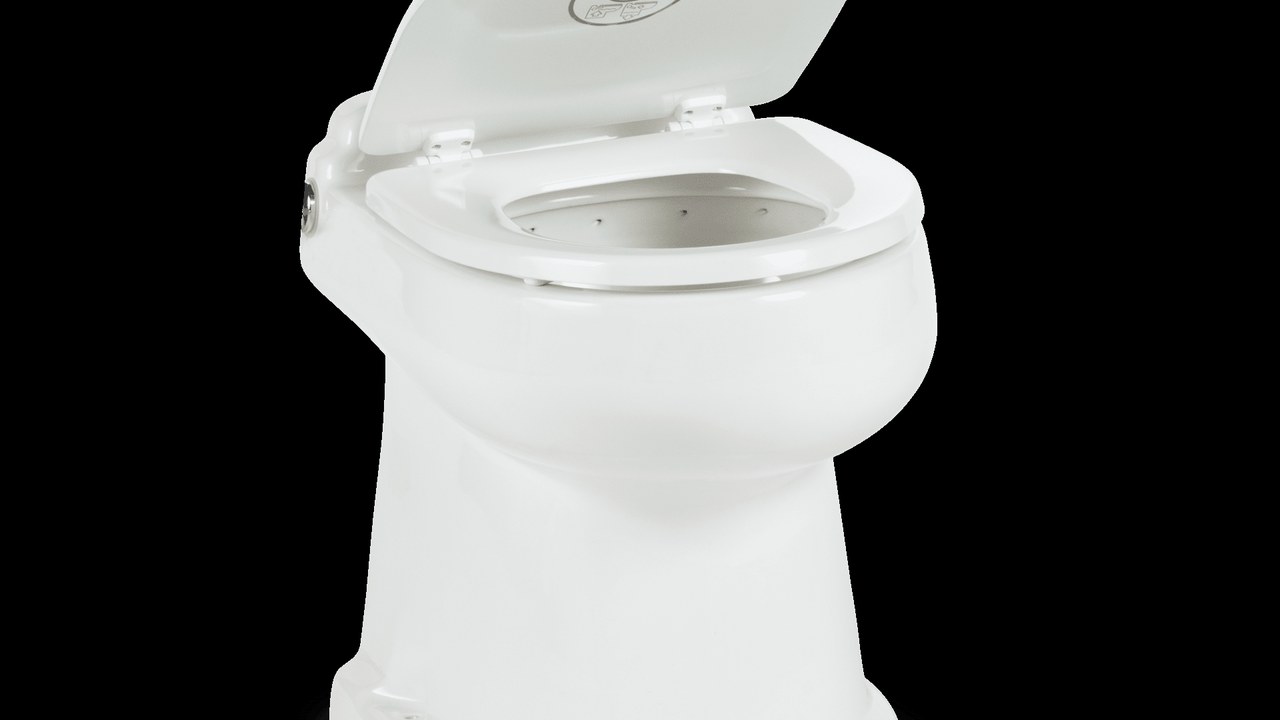
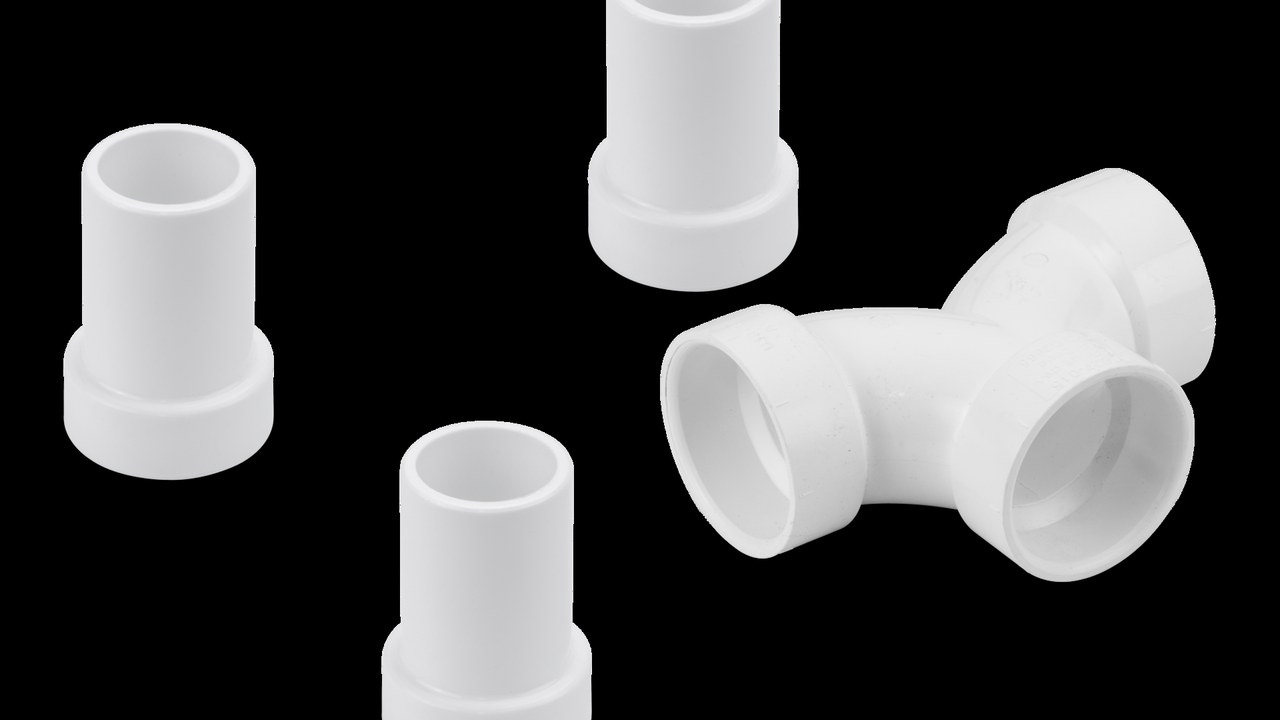
Il WC scarica al primo tentativo e non perde: è un buon inizio, ma non dimostra che il sistema sanitario sia pronto per navigare. Il collaudo deve cercare ritorni, sifonamenti, cadute elettriche, tubi schiacciati, sfiati ostruiti, sensori incoerenti e accessi impossibili prima che pareti e arredi nascondano tutto. Il catalogo Dometic comprende WC a gravità, maceratori, soluzioni a vuoto, pannelli e monitor; il tecnico identifica la variante esatta perché tensione, altezza, acqua di lavaggio e comando possono cambiare all’interno della stessa famiglia. la procedura parte con acqua ed energia isolate, serbatoio in condizione nota, passascafo controllati e area protetta. Ogni prova utilizza liquidi puliti e metodi non distruttivi, senza simulare intasamenti, bypassare protezioni o scaricare dove non è consentito. Le misure vengono annotate con punto, strumento, stato del banco, fase del ciclo e limite di arresto, così un risultato può essere ripetuto dopo manutenzione. Il tecnico verifica la rete completa dalla presa o dal serbatoio dell’acqua fino al punto di raccolta e sfiato, perché un componente efficiente può fallire dentro un’installazione incoerente. La consegna è chiusa soltanto quando l’equipaggio sa isolare il sistema, riconoscere un serbatoio vicino al limite e applicare la modalità degradata senza contaminare altri spazi. Prima del montaggio definitivo vengono confrontati i punti di servizio con il locale arredato, includendo pannelli, cerniere, oggetti stivati e spazio necessario a raccogliere eventuale liquido residuo. Il controllo non presume che due prodotti della stessa serie abbiano morsetti, pompe o raccordi identici: ogni codice viene seguito fino alla propria documentazione e alla propria targhetta. Quando un valore non è dichiarato dal produttore, il tecnico non lo inventa e non lo trasferisce da un modello simile; definisce invece una prova sicura e registra il risultato osservato. La sequenza separa ispezione, prova a vuoto, ciclo idraulico e misura elettrica, così una conformità parziale non viene presentata come accettazione dell’intero impianto. Gli accessi vengono richiusi fra prova e consegna per confermare che la configurazione finale non schiacci tubi, sposti cavi o modifichi la ventilazione del vano tecnico. Ogni anomalia riceve una causa verificata o resta formalmente aperta; silenziare un allarme o asciugare una traccia senza diagnosi non costituisce una riparazione.
Identificare ogni componente prima della prova
Si fotografano targhette, codici, tensioni, pannelli, sensori, pompe e serbatoio. La variante viene confrontata con manuale e schema disponibili. Raccordi e tubi privi di identità restano aperti fino alla verifica. La configurazione as-built prevale su etichette ereditate o preventivi non aggiornati. Il verbale riporta inoltre data di fabbricazione o revisione quando disponibile, versione dei documenti consultati e fotografie sufficienti a distinguere varianti esteticamente simili.
Mettere il sistema in sicurezza
Acqua, alimentazione e possibili energie parallele vengono isolate con una sequenza dichiarata. Valvole e interruttori sono sotto il controllo del responsabile della prova. Il serbatoio parte da un livello noto e lo scarico non viene azionato verso l’ambiente. Guanti, assorbenti e contenitori sono disponibili prima di aprire una giunzione. Prima di iniziare viene concordato un segnale unico di arresto; chi lo riceve interrompe il ciclo senza cercare di completare la misura o svuotare la tazza.
Controllare base, fissaggi e ingombri
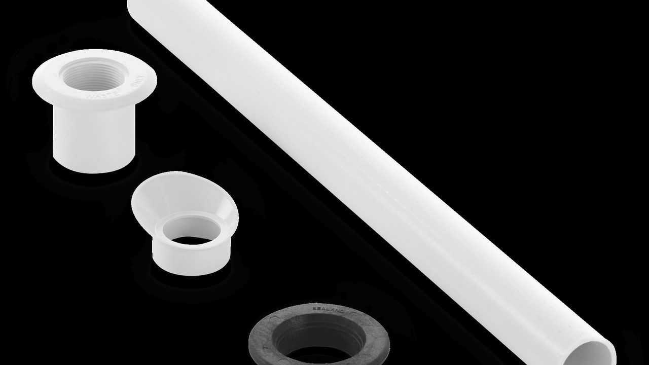
La tazza non deve muoversi né scaricare carichi su superfici fragili. I fissaggi restano accessibili e protetti dall’acqua. Coperchio, porta e persona non interferiscono con pannelli o valvole. La rimozione futura della pompa viene simulata con attrezzi reali, senza smontare arredi strutturali. Il controllo comprende la faccia inferiore del basamento e le zone nascoste da guarnizioni decorative, dove una piccola infiltrazione può restare a lungo senza essere visibile.
Costruire la matrice di accettazione
Ogni riga contiene componente, requisito, metodo, strumento, risultato e responsabile. Le prove a vista, elettriche, idrauliche e funzionali restano distinte. Una verifica non eseguita non viene segnata conforme per analogia. Dopo una correzione si ripetono tutti i controlli influenzati. Le evidenze vengono archiviate prima e dopo la correzione, includendo valore atteso, valore misurato e tolleranza ricavata dal documento applicabile al componente.
| Blocco | Decisione | Prova di accettazione |
|---|---|---|
| WC | Gravità, maceratore o vuoto; profilo e alimentazione | Identità, ingombri e ciclo completo |
| Acqua | Mare o dolce, portata, valvole e antisifone | Riempimento controllato e assenza di ritorni |
| Scarico | Tubi, curve, pendenze e serbatoio | Trasferimento senza perdite né ristagni |
| Controllo | Pannello, sensore livello, consensi e allarmi | Comandi inequivocabili e allarmi verificati |
| Consegna | Uso, isolamento, pulizia e modalità degradata | Verbale, schema as-built e prova equipaggio |
Verificare l’acqua di lavaggio
Origine, valvole, filtro, pressione e portata vengono confermati sulla configurazione installata. Il circuito di acqua dolce è protetto da ritorni secondo il progetto. La presa a mare, quando presente, viene ispezionata con la barca nella condizione appropriata. Il ciclo deve riempire senza spruzzi, ritardi anomali o alimentazione continua. Con la pompa ferma si osserva per un intervallo definito che il livello non continui a salire; l’esito viene registrato invece di affidarsi a un controllo istantaneo.
Rilevare linea di galleggiamento e sifoni
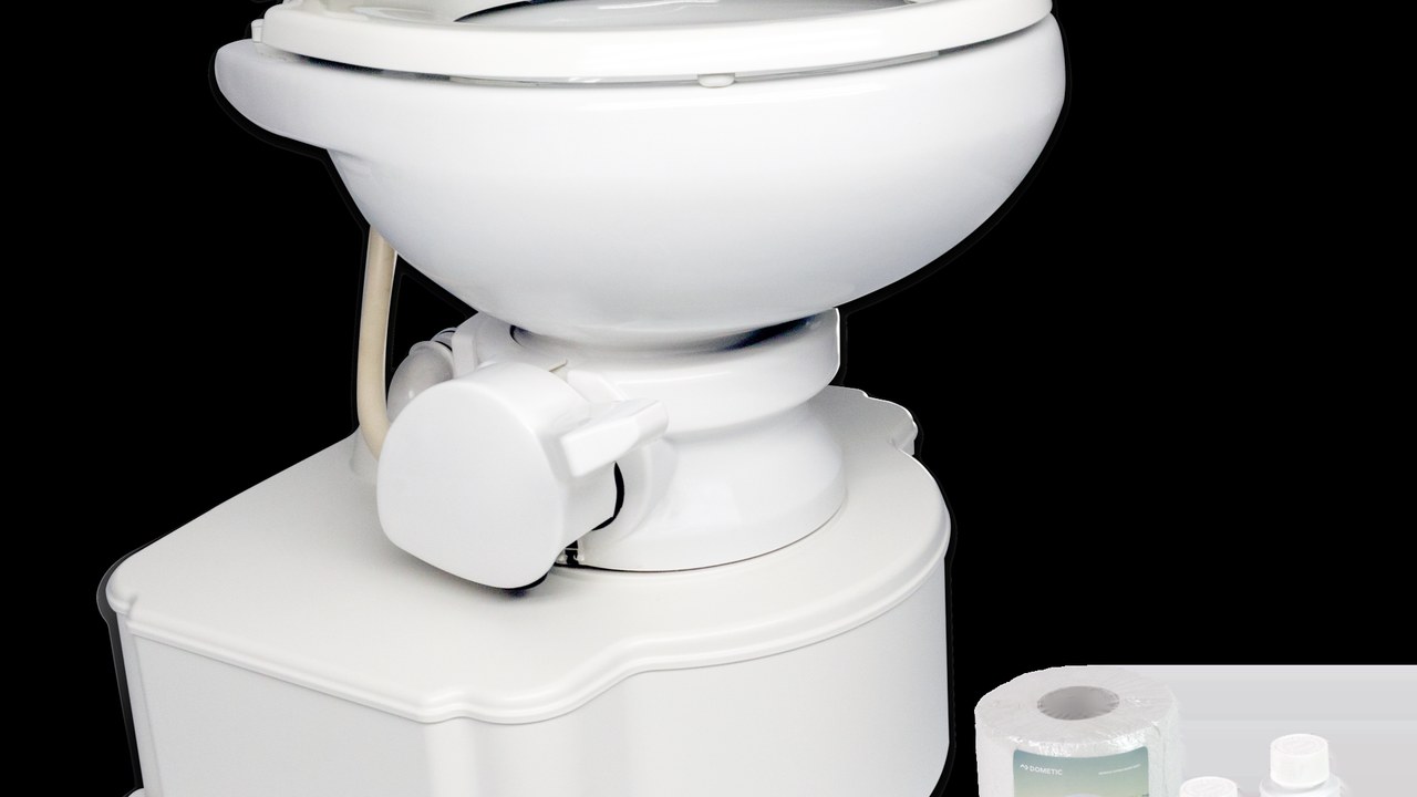
I punti alti e bassi dei tubi vengono confrontati con assetti prevedibili della barca. I dispositivi antisifone sono identificati, orientati e accessibili. La prova cerca variazioni di livello a pompa ferma senza creare condizioni pericolose. Ogni percorso non leggibile viene riportato nello schema prima dell’accettazione. La posizione delle valvole viene marcata e fotografata in assetto normale, poiché un’etichetta nascosta o capovolta può ritardare l’isolamento quando la barca è inclinata.
Ispezionare tubi, curve e raccordi
Diametri, materiali e connessioni corrispondono alle indicazioni del sistema. Non sono accettati schiacciamenti, raggi troppo stretti o sfregamenti. Fascette e supporti sono integri, orientati e raggiungibili. Tratti che trattengono liquido vengono corretti o dichiarati con una procedura di gestione documentata. Dopo il serraggio si applica una marcatura di controllo dove appropriato e si verifica che le fascette non danneggino il tubo né lavorino sul bordo del raccordo.
Provare lo sfiato del serbatoio
Il percorso viene seguito dal serbatoio al terminale, cercando pieghe e ostruzioni. Il terminale resta protetto e lontano da aperture sensibili secondo l’installazione. L’eventuale filtro è asciutto, orientato e sostituibile. La risposta del serbatoio durante riempimento e svuotamento non deve indicare sovrapressione o depressione anomala. La verifica del terminale include spruzzi, reti protettive e accessibilità dall’esterno, ma non introduce pressione artificiale che possa danneggiare serbatoio o tubazioni.
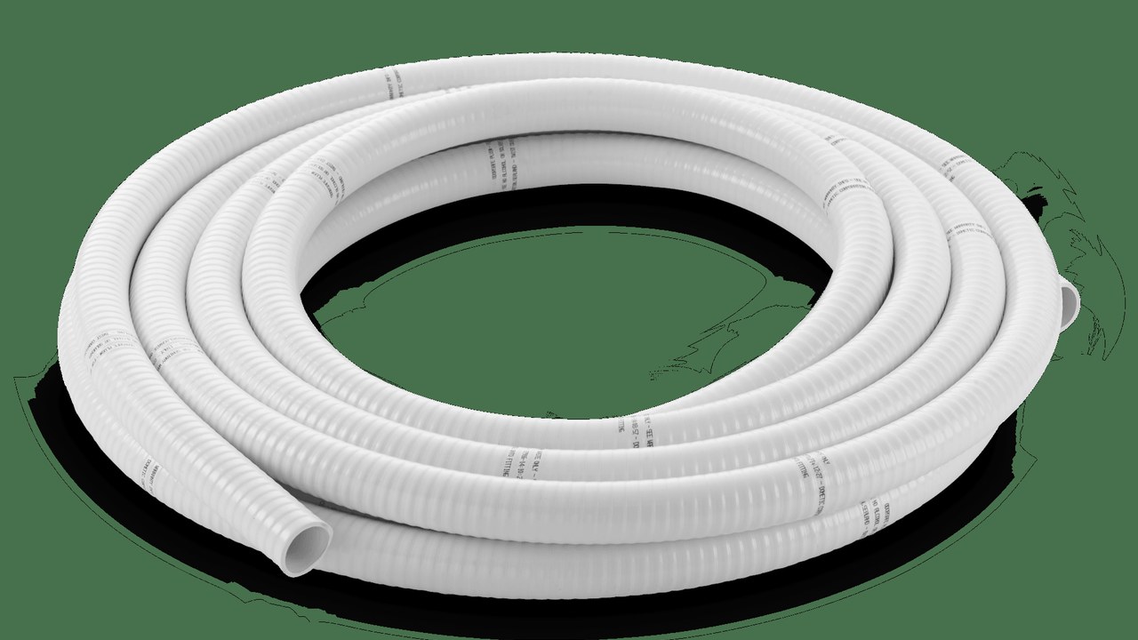
Confermare capacità e livello reale
Il sensore viene confrontato con condizioni di riempimento note e non con una singola lettura. Soglie e allarmi sono registrati nel verbale. Il volume non utilizzabile dovuto a forma, assetto o posizione dei raccordi viene considerato nell’autonomia. La procedura vieta di usare il bordo del serbatoio come metodo ordinario di calibrazione. Fra due punti di calibrazione il tecnico annota volume introdotto e assetto della barca, perché inclinazione e geometria possono modificare la risposta di alcuni sensori.
Collaudare il maceratore
Alimentazione e tubazioni vengono controllate prima di avviare la pompa. Il ciclo usa soltanto materiale ammesso e acqua pulita nella fase iniziale. Corrente, durata, rumore e vibrazione vengono registrati. Un rallentamento, un intervento di protezione o un terminale caldo impongono arresto e diagnosi. La pompa viene lasciata raffreddare tra cicli quando richiesto e non si usa l’intervento della protezione come normale fine prova, poiché quello è già un risultato anomalo.
Cercare perdite nei sistemi a vuoto
La rete deve raggiungere e mantenere il comportamento previsto senza avviamenti inspiegabili. Giunzioni, guarnizioni, generatore e accumulo vengono osservati separatamente. La ricerca non usa pressioni o sostanze non autorizzate. Il tecnico registra tempi e condizioni per confrontare il sistema dopo interventi futuri. Un avviamento periodico senza utilizzo viene trattato come possibile perdita di tenuta; frequenza e durata vengono misurate prima di intervenire sulle giunzioni.
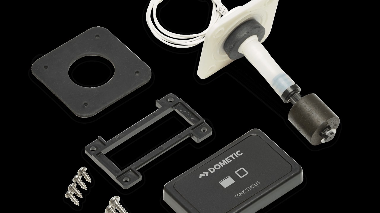
Misurare tensione e caduta sotto carico
La tensione si rileva al banco e al dispositivo durante la stessa fase del ciclo. Sezione, lunghezza, terminali e protezione sono confrontati con il modello reale. Il valore a riposo non assolve un circuito che cede durante l’avvio. Cavi e connessioni restano separati dai liquidi e ispezionabili. La caduta viene calcolata sulla differenza simultanea e correlata alla corrente, evitando confronti fra letture prese in momenti o stati di carica differenti.
Provare pannelli e consensi
Ogni tasto deve produrre il comportamento indicato senza sequenze ambigue. Le postazioni vengono provate una alla volta e poi secondo la logica prevista. La perdita di acqua, energia o consenso deve portare a una condizione comprensibile. Nessun ponticello temporaneo resta installato dopo la diagnosi. Dopo ogni comando il tecnico conferma arresto completo e assenza di alimentazione inattesa, quindi prova il ripristino dalla stessa condizione iniziale documentata.
Verificare monitor e allarmi
Pannello, sensore e alimentazione vengono identificati come un sistema unico. Le indicazioni sono confrontate con livelli noti in più punti. Un allarme viene provato con metodo sicuro senza forzare il serbatoio oltre il limite. L’equipaggio deve distinguere livello, guasto sensore e assenza di alimentazione. L’eventuale monitor remoto non assolve il pannello locale: alimentazioni, perdita della comunicazione e indicazione di guasto vengono controllate come stati differenti.
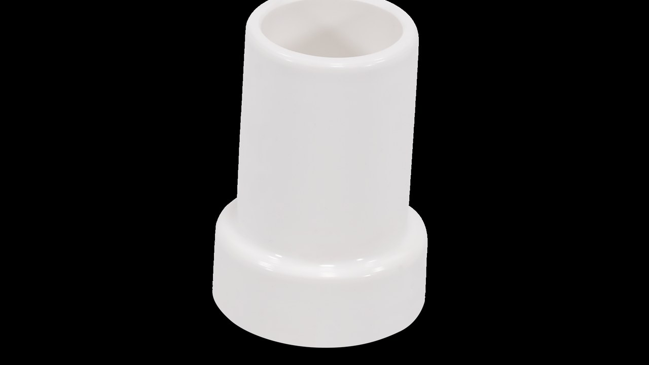
Controllare perdite dopo più cicli
Il sistema viene asciugato prima della prova per rendere visibile ogni nuova traccia. Si eseguono cicli intervallati coerenti con il manuale e con il profilo d’uso. Raccordi, base, pompa, serbatoio e sfiato vengono ispezionati con luce adeguata. Una goccia non viene attribuita a condensa senza evidenza. Terminati i cicli, carta assorbente pulita viene passata sotto ogni raccordo accessibile; la fotografia del controllo entra nel fascicolo con ora e condizione del sistema.
Registrare rumore, vibrazione e temperatura
Il riferimento viene raccolto nella posizione dell’utente e vicino alla macchina. Vibrazioni trasmesse alle paratie possono indicare supporti o tubi in tensione. Temperature anomale su motore, cavi o connessioni chiudono il collaudo. I valori finali vengono conservati per la manutenzione predittiva. Le temperature sono rilevate nello stesso intervallo dal termine del ciclo; cambiare ritardo o punto di misura renderebbe il confronto successivo poco significativo.
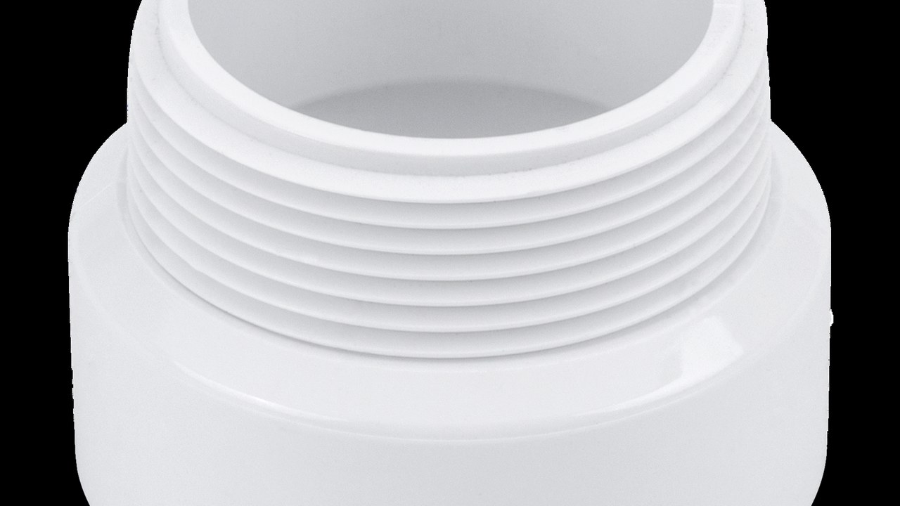
Provare isolamento e modalità degradata
L’equipaggio individua valvole, interruttore e dispositivo di raccolta senza suggerimenti. Il WC viene messo fuori servizio in modo chiaro quando una parte non è disponibile. La procedura evita scarichi, ritorni e riattivazioni accidentali. Attrezzi e ricambi essenziali sono realmente raggiungibili a barca allestita. La procedura degradata specifica anche chi può riattivare il sistema e dopo quali verifiche, impedendo che un cartello rimosso sostituisca una diagnosi chiusa.
Chiudere il fascicolo as-built
Schemi, codici, fotografie, misure, tarature, limiti e manutenzione vengono consegnati insieme. Le etichette fisiche coincidono con il documento finale. Ogni non conformità residua riporta responsabile e condizione necessaria alla chiusura. Il collaudo termina quando impianto, verbale ed equipaggio raccontano la stessa configurazione. Prima della firma l’equipaggio esegue un ciclo, legge il livello, isola il circuito e descrive i limiti senza suggerimenti, fornendo una prova concreta della consegna.